Designs Final Design
Final Design
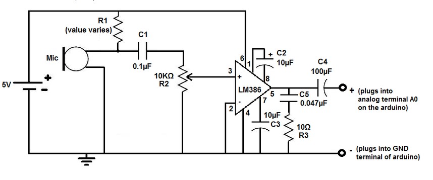
This is the schematic of the newly designed microphone amplifier circuit that is present in the final design. It was designed following a guide, with R1, the pull up resistor, chosen to be 6.8 kOhms. This value was chosen because it resulted in the best response when a range of 10 resistors ranging from 1.8 to 10 kOhms were tested.


This is the response of the amplifier measured on the Agilent Technologies, Infiniium oscilloscope with the 1.8 kOhm, 6.8 kOhm (chosen), and 10 kOhm resistors respectively.
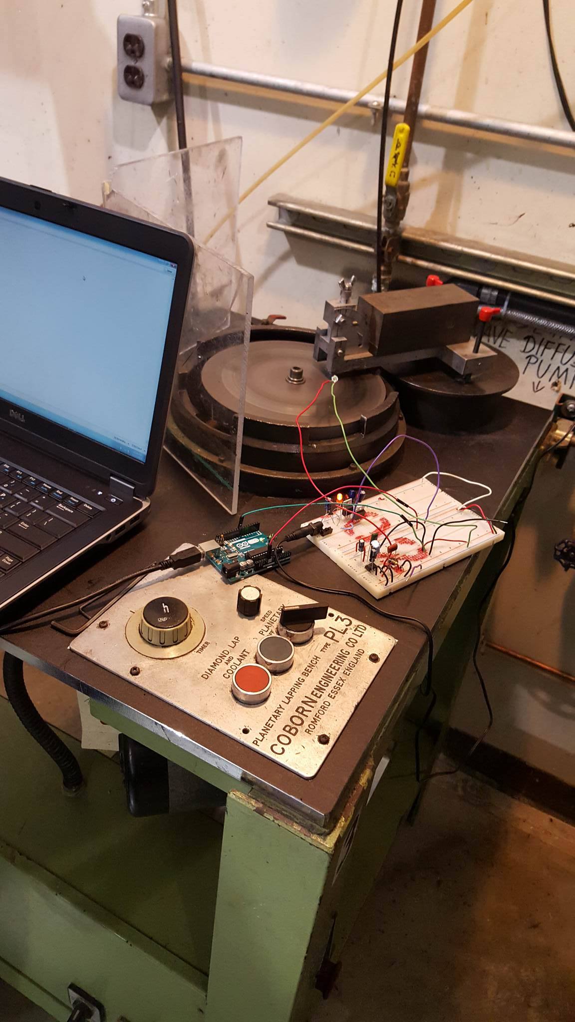
Our final design, which doesnt have the display, accelerometer, or alarm. The team was only testing for the accuracy of the microphone on the serial monitor.
The results were within a couple Hz when tested during construction, and even matched the analyzed measurements take before the first prototype.
Final Design packaging
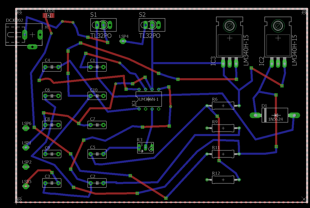
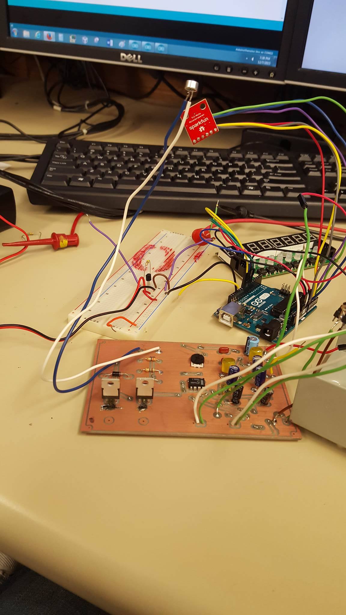
For the final design packaging we decided to put out system onto a printed circuit board (PCB).
Left, we have the layout of the final designed system made on with the software Eagle.
On the right, is the completed PCB with all components soldered in place and devices connected.
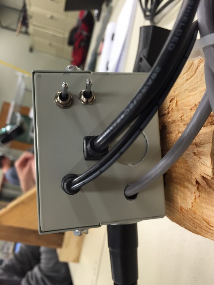
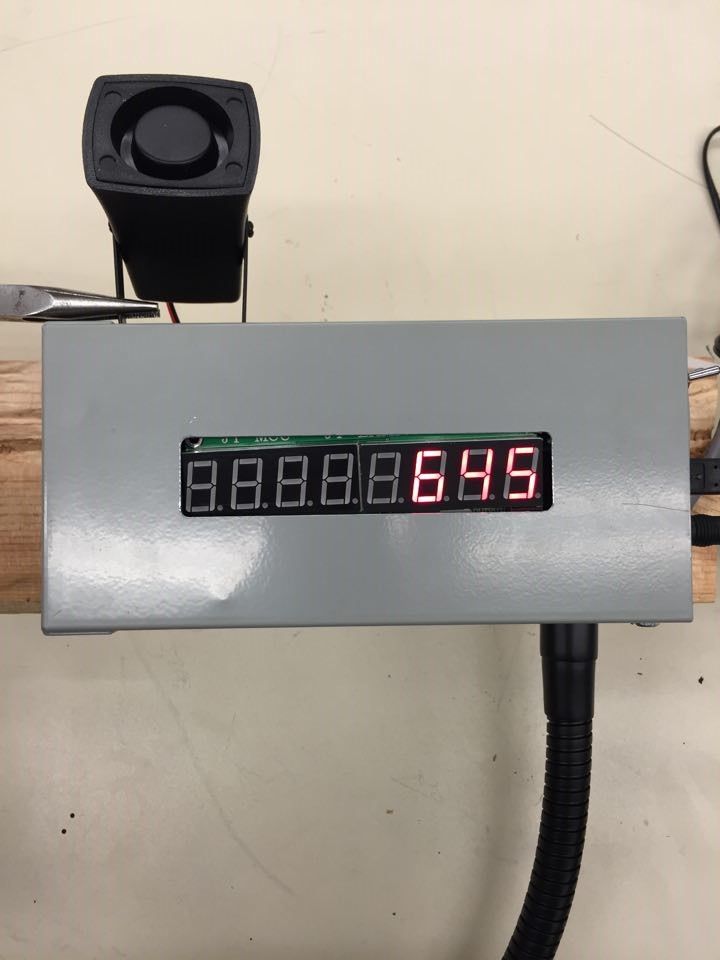
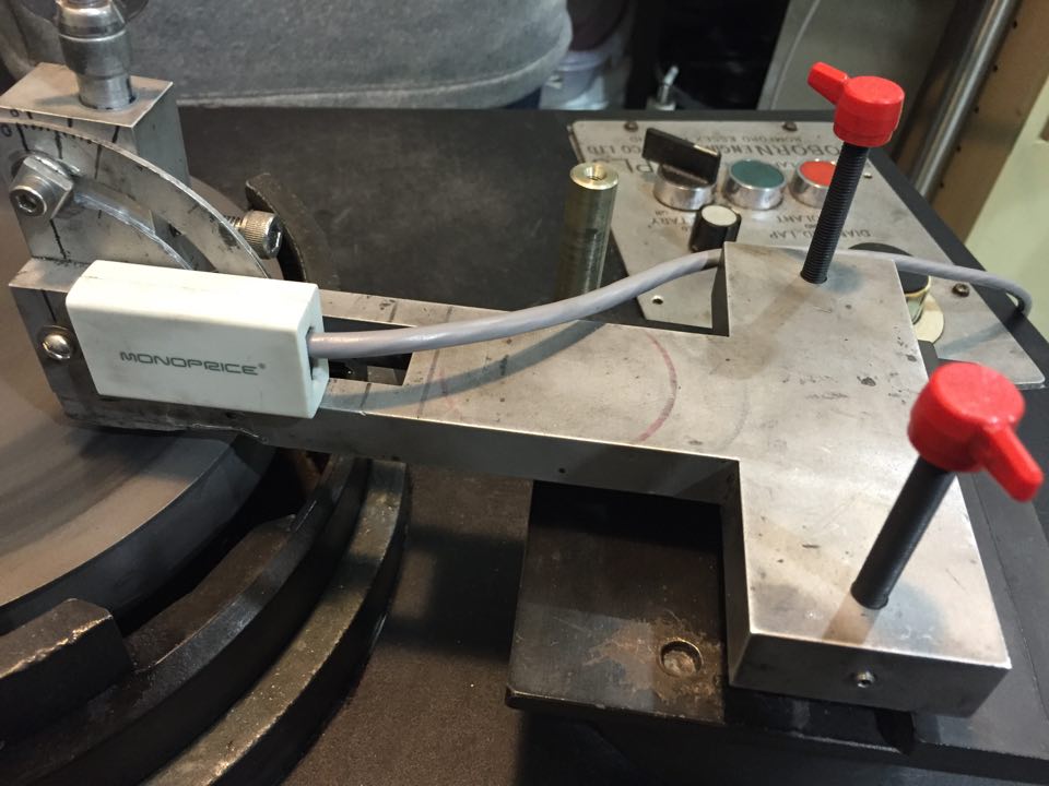
The packaging of the system consists of a metal box enclosure, with one end drilled out for the ports and cords (Left).
The enclosure shown (Center) put together for the first time.
The packaging of the accelerometer shown on the arm of the diamond polishing machine (Right).
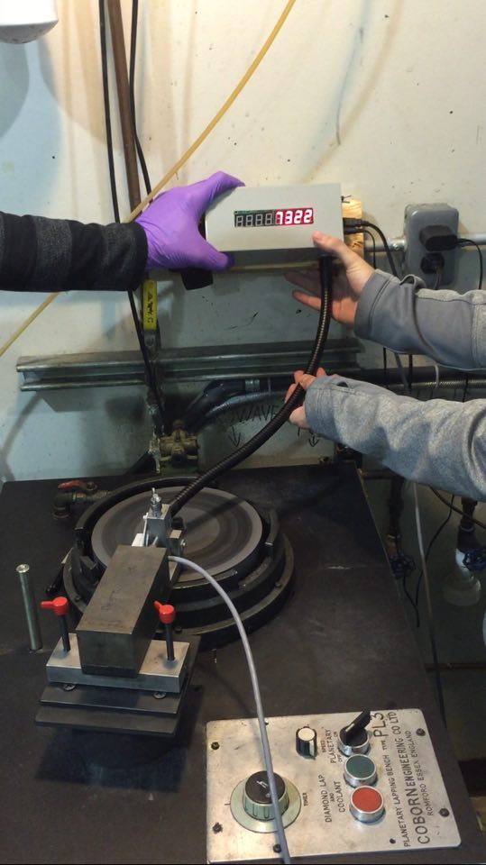
With the final design packaging nearly completed, the team took the design in to Fraunhofer USA to demonstrate and show the sponsor, Aaron, the progress. Durring the vist the mounting location was decided.