
This was our initial attempt at designing some of the necessary specifications for the project. Here we built a battery charger circuit that will turn itself off when the backup battery reaches a certain voltage. This can be seen in part C of the picture. We also built a power circuit that would take a +ve/-ve 12V power supply and transform it into whichever voltage we desired (5V and 3.3V) this can be realized in part D. We need to downscale a voltage or current signal, as well as shift it up by 2.5V so that the microcontroller can sense it properly. We built an adjustable summing op-amp circuit to sum a DC that we can adjust with the AC voltage or current signal. This can be seen in part A. In the event that the design loses its exterior power, our battery will be needed to power the microcontroller. Therefore, we designed a switch over scheme to enable the battery power the microcontroller in the occurrence of such a scenario. We used a DPDT relay to switch the power over, as well as give a signal to the microcontroller that it is on back-up power. This stage also saw us introduce our microcontroller. We chose the Arduino Yun because of its Ethernet and USB capabilities for other specifications that have yet to be designed.

In this stage, we expanded upon our previous stage, correcting designs and adding a new feature. We found that it would be a good idea to add a cutoff switch for the microcontroller so that we could isolate it from the rest of our circuit while performing any tests. This was a protective measure because it was the most expensive part of our design. We also found that the microcontroller requires a significant amount of power. One of our voltage regulators in the power circuit would get extremely hot while powering the microcontroller. Therefore, we added a heat sink to it as can be seen in the lower right part of the figure. The new feature that we added was a capacitor bank control contact; which would receive a close signal If the power factor gets too low. We used another DPDT relay to handle closing the control contact as well as lighting an LED to indicate it is sending a close. We forward bias a transistor using the microcontroller to pick up the relay.

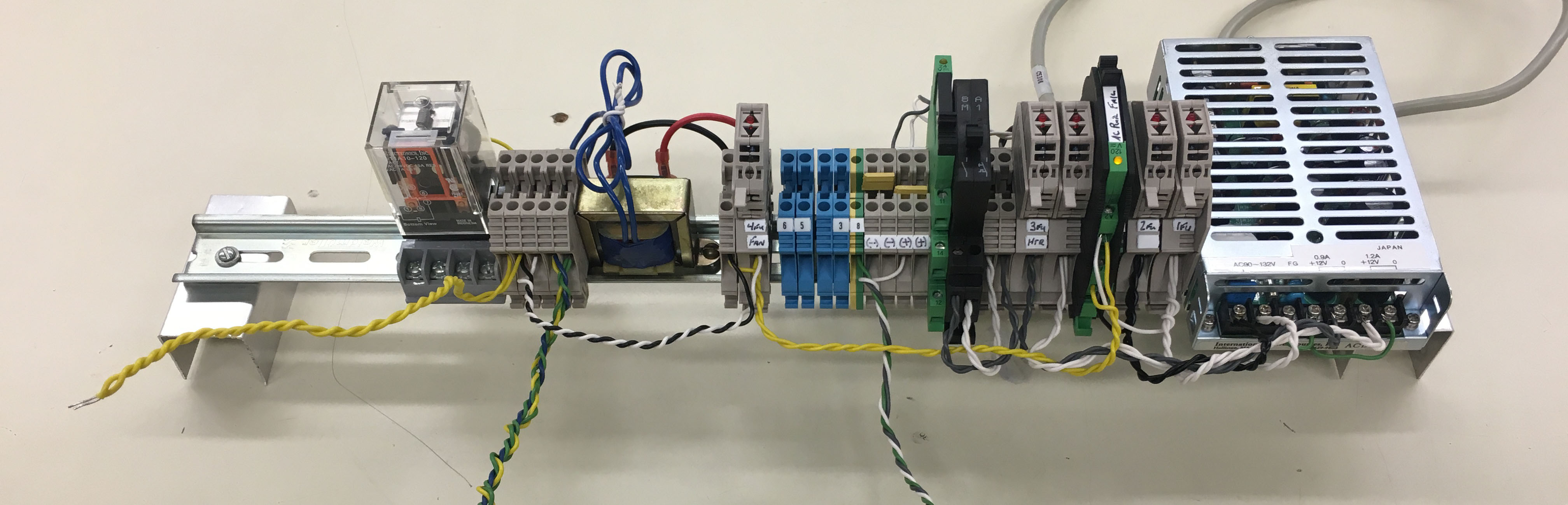
Here we developed our design for the power supply to the circuit, as well as a stronger capacitor bank contact, and a transformer with the ability to sense wall outlet voltage. For the power supply, we connected a 3 prong power cord to a set of fuses for our protection. From the fuses, the power goes to an AC to DC power supply that creates the +ve/-ve 12 V power needed for our circuit. Again, we fused the DC power and ran it through a switch so that we could turn the circuit on and off. For the capacitor bank control contact, we applied 120V AC to one side of the larger relay seen on the left side figure. We then used our original DPDT relay to close the other side of the 120V AC to the larger relay when necessary. This will pick up the coil and close a larger contact that can handle much more power than our original design. We also added the transformer as seen in the figure. This was designed to step 120V AC down to a signal that can be applied to a circuit board. We attach this to the same AC voltage we are using to power the circuit. This was to establish the availability to sample one voltage with the microcontroller.

In stage 4, we began assembling our first prototype. We found a box that was similar to the size specifications provided by our sponsor. Here we took the same equipment we had from the previous stages and mounted it neatly within a box. We added two more transformers for 2 more voltage signals and added fusing to then in case of a fault. We also added connections linking our design to the outside of the box. We have a port for the Ethernet plug, as well as a power cord plug on the side of the box. We also have the capacitor bank control contact available on the side of the box. We ordered 4 LCD displays that will go on the outside of the box in the final design. We wanted to avoid using all of the microcontroller pins for the displays, and therefore elected to use I2C communications and adapters on the screens as can be seen. Eventually, the design will allow a user to adjust tolerances and other specification using pushbuttons on the front panel. To simulate this, we added four momentary push buttons to the right of the LCD screens. The last edition to the hardware in this stage was a fan to cool the 5V voltage regulator. This can be seen on the side of the box. With the heat sink in the previous stages, we were able to power the microcontroller safely. However, the addition of four LCD screens drew too much power and we were forced to cool the regulator further. We recognize this as an issue with our design and plan to correct it with future design.

It was brought to our attention that although it may be standard to have sections of 120 AC exposed in factories or utilities, it was not safe for college design courses. We found some Plexiglas and mounted it to protect the few sections of exposed 120V in the top of our box. The design specifications also call for an alarm light to turn on for any voltage imbalance and to remain on until acknowledged by an operator. We created a design similar to that of the capacitor bank relay to turn on an amber alarm light on the side of the box near the transformers and protected by the Plexiglas. We used yet another DPDT relay so that it could lock itself on once picked up. A simple normally closed push button was used as the reset button. This design can be seen between the LCD screens in the figure.

Represents the first step of the final design. The team used the Eagle Printed Circuit Board (PCB) software to design a circuit board that could do all of the functions that our proto-board circuits could do. We designed a pin out so that our micro controller could land directly onto the PCB. We also used screw terminal to ensure any external signal could land onto the board and be tightened down, while retaining the possibility to be disconnected easier than unsoldering something. The ECE shop at Michigan State University was able to fabricate the board using a through-hole design. Three push buttons were added that can be used for logic into the Microcontroller, but are not used at this time. All calculations were made to ensure a 50% tolerance on all traces for the current that would be passing through them.

Stage 8 is not part of the final design, but is needed as a representation of what will take place in the factory outside of our project. The box that we have designed takes small signals of current and voltage into it to ensure the operators safety. 480V should never be applied in a box where users would have direct contact. Therefore, to simulate what will be done external to the box, we created a separate box that will take large currents and voltages and convert them to something that can be connected to our final design. We used the same three transformers that stepped 120V down to 13.5V and connected the three current transformers to loops where they could measure a current load. We connected these smaller signals to banana plugs that were mounted on the side of the box. Here is where we can connect banana adapters to the terminals to create a connected between the transformer box and our product. For testing purposes, we added a power strip on the left side of the box to enable us vary the load and watch the current and power readings change. For safety, a piece of Plexiglas was installed on the top of the box to separate users from open voltages while still granting viewing access.


Once a PCB was created, we began stage 7, where we constructed the rest of the hardware for the final design. We worked with our sponsor in acquiring parts such as industrial lights, pushbuttons, and a box suitable to be placed in the factory our project was designed for. We used many tools such as jigsaws, drills, taps, and hole punches in constructing the product.

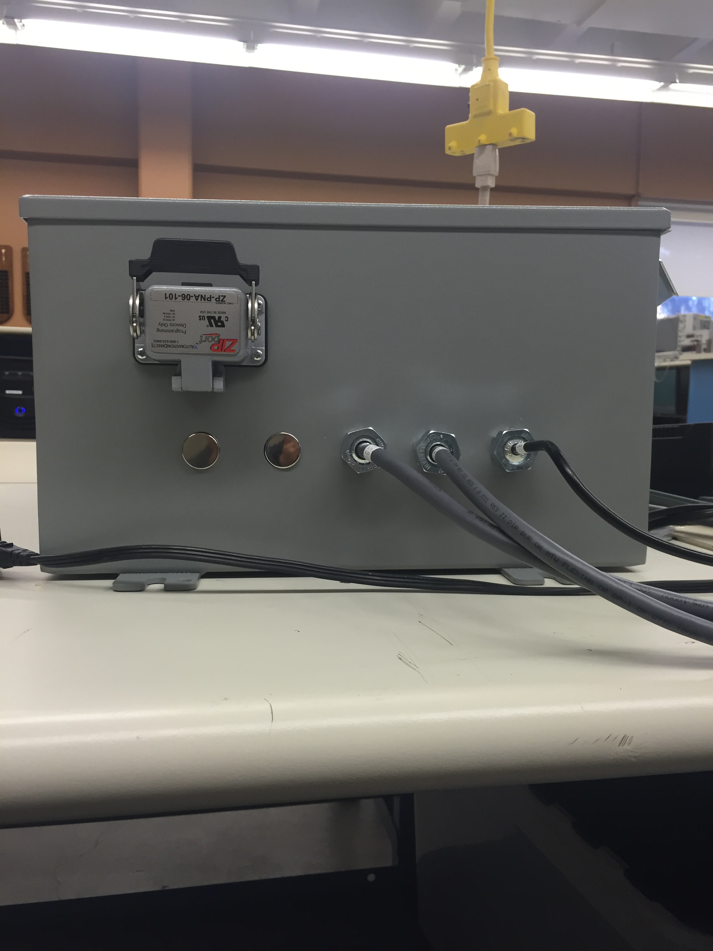

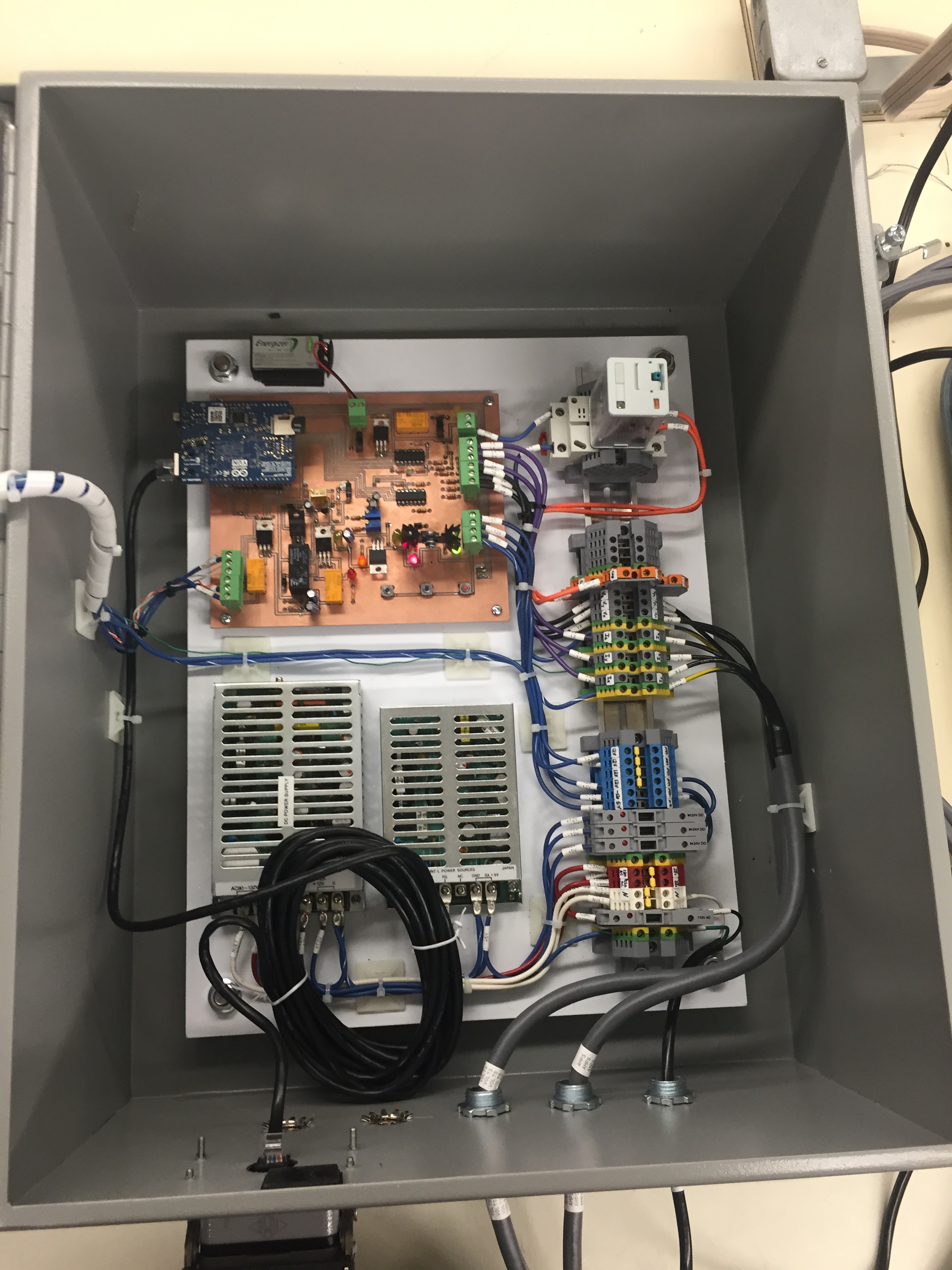
Top Bottom Inside Inside
Stage 9 occurred concurrently with stage 8, but involved the assembly of our final design. With the power supplies, PCB, knobs, buttons, lights, and terminal blocks picked out, we brainstormed the most logical and efficient layout for the final panel. We used either self-tapping screws or taps to connect everything within our box to avoid the necessity for tightening objects from the back side. We were especially careful in the selection of wire color for each component and used a wire code similar to how our sponsor builds their panels to avoid confusion once the design is implemented. Much care was also taken to ensure the wires were labeled and organized in a comprehensible and neat manor. Industry standards were also followed when landing any outgoing signal on the exterior of the terminal block, and interior functions on the other side. Because our design is intended for direct implementation into a professional environment and is not just a simple “concept design”, our group put in extra effort to ensure our device met professional standards. The goal of this stage was to deliver the final product as any other professional engineering firm would.