ECE 480 Team 5:
Interactive Radar Demonstration
Radar concepts
 Introduction
Radar
(an acronym for Radio Detection And Ranging) is a widely-used technology for detecting
the presence, position, and speed of objects. A simple radar system has an
antenna and a circuit or a computer which calculates and displays the position
or speed of the target. The antenna emits radio waves in a particular
direction. The radio waves bounce off of objects in the path and return to the
antenna, where they are picked up and turned into an electrical signal. The
computer compares the reflected wave’s characteristics with those of the
transmitted wave to determine the target’s position or speed.
In
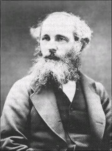
the latter half of the 19th century, the experiments of J.C. Maxwell
(shown at right) and Heinrich Hertz laid the foundations for radar and, more
generally, all modern wireless technology. Following much experimentation of
his own, Maxwell corrected, verified, and consolidated mankind’s
knowledge of electricity and magnetism into an elegant set of equations known
today as Maxwell’s laws. Using Maxwell’s theory, the German
physicist Heinrich Hertz, for whom the SI unit of frequency is named,
demonstrated that electromagnetic waves travel at the speed of light, and that
they can be reflected off objects. In the early 20th century,
experimenters like Marconi and Tesla postulated a radar-like device, building
on the work of Maxwell and Hertz. In 1904, the German Christian Hülsmeyer was able to demonstrate a very crude radar
system for the purpose of detecting ships at sea to avoid collisions. His
system was incapable of calculating range – it merely rang a bell if it
detected an object in the beam path – but it was an important step in the
development of modern radar.
In
an age that saw the introduction of aircraft, submarines, and other advanced
vehicles into military fleets, the ability to detect these new, deadly vessels
from a long distance appealed very strongly to high commands around the world.
During the interbellum, no less than ten different
countries researched and developed radar technology, all in secret, and with
the belief that they each possessed a unique technology that would provide a
significant military advantage. In 1935 the Scot Sir Robert Watson-Watt
successfully detected an aircraft’s position using radar. This successful
experiment led to the development of the world’s first operational radar
network, named “Chain Home”. Since the Second World War radar
technology has been improved upon significantly, and it is now an integral and
familiar component of military technology.
Despite
its military heritage, radar has found many applications in the civilian world.
Meteorologists use Doppler radar to detect the motion of precipitation in the
atmosphere; automotive manufacturers include radar units on their vehicles to
detect objects in the path of a vehicle in reverse; members of law enforcement
use radar guns to catch speeding motorists, and baseball scouts use similar
radar guns to measure the velocity of pitches; air traffic controllers use
radar to track activity in the airspace of their jurisdiction… the list
goes on. Most people are familiar with radar, but not many know how or why radar
works. Hopefully after reading this page, you will understand how basic radar
systems work.
How Radar Works
Simply
put, radar exploits the phenomenon of electromagnetic wave reflection to
characterize a target environment. In military use, this could mean scanning
the ocean surface around a naval vessel to detect enemy vessels; in civilian
use, this could mean scanning the atmosphere to detect cloud activity. A basic
radar system, shown below, consists of a transmitting source, a
switch/circulator, an antenna, and a receiving/processing unit with some kind
of display.
 The transmitter generates the
high-frequency radar signal. The frequency of the signal can be changed to best
suit the specific application, i.e. to optimize range resolution for imaging
technology, to maximize range of operation, to penetrate materials opaque to
other frequencies, etc. The radar signal passes through a special type of
connector, called a switch or, more commonly, a
circulator, to the antenna,
where the signal radiates outward in a beam whose shape is defined by the
geometry of the antenna. The waves reflected off targets make their way back to
the antenna, where they are picked up and converted into an electrical signal.
The circulator is a device which allows signals to be sent in only one
direction. It prevents the transmitted signal from making its way into the
receiver at the receiving port, and it prevents the received signal from
entering back into the transmitter. This ensures minimal conducted interference
between the transmitting and receiving stages. The receiving unit stores the received signal in memory, calculates
the desired information from differences between the transmitted and received
signals, and displays the information in a preferred format, such as the
Hollywood favorite plan position indicator (PPI) screen shown below, displaying
precipitation intensity around Madrid, Spain.
The transmitter generates the
high-frequency radar signal. The frequency of the signal can be changed to best
suit the specific application, i.e. to optimize range resolution for imaging
technology, to maximize range of operation, to penetrate materials opaque to
other frequencies, etc. The radar signal passes through a special type of
connector, called a switch or, more commonly, a
circulator, to the antenna,
where the signal radiates outward in a beam whose shape is defined by the
geometry of the antenna. The waves reflected off targets make their way back to
the antenna, where they are picked up and converted into an electrical signal.
The circulator is a device which allows signals to be sent in only one
direction. It prevents the transmitted signal from making its way into the
receiver at the receiving port, and it prevents the received signal from
entering back into the transmitter. This ensures minimal conducted interference
between the transmitting and receiving stages. The receiving unit stores the received signal in memory, calculates
the desired information from differences between the transmitted and received
signals, and displays the information in a preferred format, such as the
Hollywood favorite plan position indicator (PPI) screen shown below, displaying
precipitation intensity around Madrid, Spain.

There
are many different kinds of radar, and each has its own specific uses. Here we
will discuss only a couple of the more popular radar systems, as they are
relevant to Team 5’s radar demonstration project; however, the reader is
encouraged to further investigate these and other radar systems if he or she
finds this discussion interesting.
Doppler Radar
Doppler
radar makes use of the Doppler effect to determine the
velocity of a target. First proposed in 1842 by the Austrian physicist
Christian Doppler, the Doppler effect or Doppler shift
is the phenomenon whereby a wave’s frequency changes relative to the
motion of both source and observer. A common example is the change in pitch of
an ambulance siren as the horn on the ambulance (the source) moves toward and
away from you (the observer). As the ambulance approaches you, the pitch of its
horn increases to a maximum when the ambulance is closest to you. As it moves
away from you, the pitch of its horn decreases with distance.
To
detect velocity of a target using Doppler radar, the transmitter generates a
radar signal of frequency fo and transmits
it in a beam via the antenna. The transmitted wave reflects off the target in
the beam path and, depending on the velocity (speed and direction) of the target, undergoes a frequency change. This
reflected wave makes its way back to the antenna, where it is picked up and
sent into the receiving unit. The transmission and reflection process are shown
in the diagram below. The receiving unit compares the frequency of the
reflected signal with that of the transmitted signal, usually by
frequency-mixing or heterodyning the two signals
together. The result of this process yields the change in frequency undergone
by the reflected wave. The change in frequency fd
can be used to immediately calculate the (approximate, but very accurate for
speeds far lower than the speed of light) velocity of the target, v:

 Here, c is
the speed of light, ft
is the transmitted radar signal frequency, fd
is the frequency shift, and v is the
target velocity in the direction of the radar beam. Doppler radar is quite simple,
and this simplicity lends itself to a variety of common uses. Police and
meteorological radars are largely of the Doppler variety.
Here, c is
the speed of light, ft
is the transmitted radar signal frequency, fd
is the frequency shift, and v is the
target velocity in the direction of the radar beam. Doppler radar is quite simple,
and this simplicity lends itself to a variety of common uses. Police and
meteorological radars are largely of the Doppler variety.
There
is a variant of Doppler radar, called pulse-Doppler radar, which is used to obtain both target velocity and target
range data. This radar can detect very fast-moving objects at long distances,
and so it possesses many applications both civilian and military. Pulse-Doppler
radar is a much more complex system than regular Doppler, so we will not go
into specifics, but interested readers are encouraged to search for more
information.
Frequency-Modulated
Continuous Wave (FMCW) Radar
The
primary advantage of FMCW radar is that it can provide ranging data for targets
relatively close to the antenna. Continuous wave radars, such as Doppler
radars, cannot detect range because they have no reference point by which to
time the reflected wave. In FMCW, the frequency of the transmitted signal is
changed, or modulated, in a linear manner
up and down a small range of frequencies. Often the modulating waveform is a sawtooth wave, shown as the red wave in the image below.
For targets in motion, the Doppler effect introduces a
slight frequency perturbation represented in the image below by the quantity fD.
For the purposes of this discussion, this slight shift will be ignored.
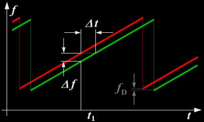 The basic idea behind FMCW is that since radio waves
travel at the speed of light, we can determine the distance of an object by
measuring the time it takes for a wave transmitted from the antenna to reach
the target, reflect off the target, and make its way back to the antenna;
however, this time delay is difficult to measure in practice. If the transmitted
wave’s frequency changes in a linear manner as shown at right, the time
delay Δt
is proportional to the instantaneous difference in frequency between the
transmitted wave and the reflected wave (shown at right as the green wave), Δf. This
instantaneous frequency difference can be obtained using the concept of
heterodyning, described in the previous section on Doppler radar. Assuming the characteristics
of the modulating sawtooth waveform are known to the
receiving unit, the target’s range can be calculated like so:
The basic idea behind FMCW is that since radio waves
travel at the speed of light, we can determine the distance of an object by
measuring the time it takes for a wave transmitted from the antenna to reach
the target, reflect off the target, and make its way back to the antenna;
however, this time delay is difficult to measure in practice. If the transmitted
wave’s frequency changes in a linear manner as shown at right, the time
delay Δt
is proportional to the instantaneous difference in frequency between the
transmitted wave and the reflected wave (shown at right as the green wave), Δf. This
instantaneous frequency difference can be obtained using the concept of
heterodyning, described in the previous section on Doppler radar. Assuming the characteristics
of the modulating sawtooth waveform are known to the
receiving unit, the target’s range can be calculated like so:

Here,
c denotes the speed of light, Δf
denotes the instantaneous frequency difference between the transmitted and
received waves, and m denotes the
slope, or change in frequency per second, of the modulating waveform. The
characteristics of the modulating waveform can be modified to optimize the
maximum range or range resolution of the radar. FMCW radar is used primarily to
detect range, as in an aircraft’s altimeter. FMCW can also be useful in
maritime navigation, as range data gathered with a rotating antenna can be
combined into an image of the surrounding environment, showing distant objects
invisible to the human eye.
References