DESIGN
|
Processor
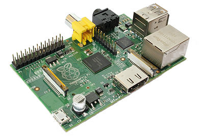
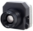
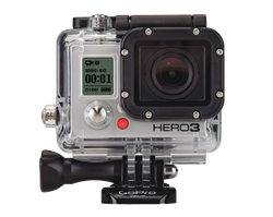
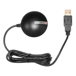
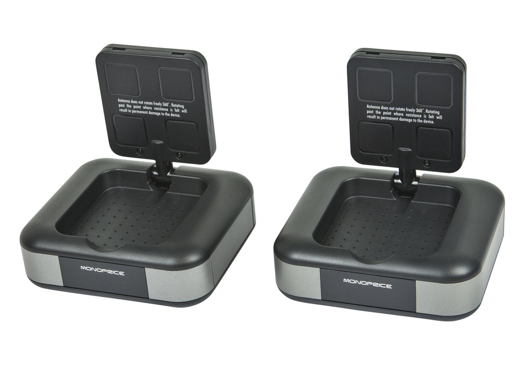
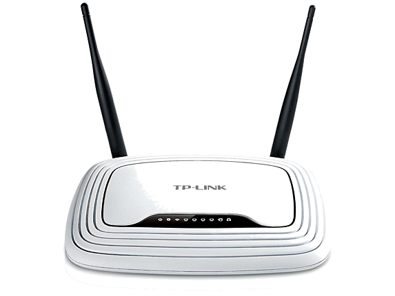
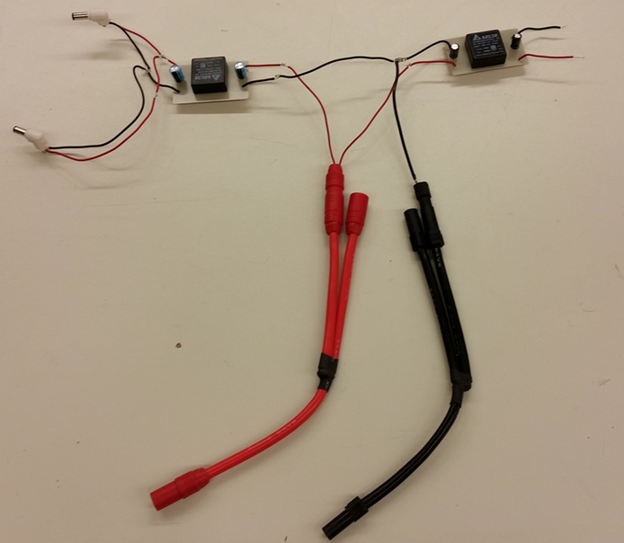
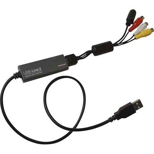
Raspberry Pi 2 As a result of the project's requirements, the Raspberry Pi 2 was chosen as the SOC. The processor was originally chosen to process all video input, but further research found video processing would be more efficient at the base station. Therefore, this processor will be used to wirelessly transfer GPS data collected from the chosen GPS device. A wireless dongle is connected to the processor to transmit this data. The team will step down the power supplied to the processor in order to provide adequate input power. Thermal Camera Tau 2 640 19mm Infrared Thermal Camera The customer has provided a thermal camera to use in the error detection process. The camera will be used to detect large amounts of heat dissipated from wires in problematic areas. When a problem is detected, video is to be recorded from the thermal camera. This device is crucial to the operation of the sub-system. Video GoPro Hero3 HD Camera As provided by the customer, a GoPro camera will be used to provide video of the problematic site. The use of the camera will be to assist the user in recognizing a problem area the thermal camera detects. This video will also be used for after flight processing to help the customer determine the easiest resolution to the problem. GPS GlobalSat BU-353S4 Although the choice of which imaging sensors to use was invariable, choosing the GPS module was up to the team. When a potential problem is detected, the GPS information will be sampled and used to plot the location to Google Maps. This GPS will connected to the Raspberry Pi. Transmission Monoprice 5.8 GHz wireless audio/video transmitter and receivers In order to transfer data from the two cameras in the system, these transmitters and receivers were selected. Each camera will be tethered to a transmitter which will, in turn, wirelessly transmit the data to their corresponding receiver at the base station. Router TP-Link N300 Home Router - 300Mpbs The router selected for the prototype of our project will not be used by the sponsor. This router is used to simulate having wireless capabilities at the base station. The pilot of the UAV will be at the base station, more specifically, a truck that will have a wireless hot spot. The components on the UAV are all operating under the router’s subnet, which is located on the base station. The router acts as the central hub where all data passes. The front-end software connects to the back-end through the router. Power Supply 5V and 12V power converters created by the team The UAV comes with a 22V Lithium-Polymer Battery. This battery will provide power to the UAV and all the components created in our sub-system. These components operate at either 5V or 12V so the power must be stepped down to prevent any damage. Circuit boards were designed to implement the Delta S24SE05003 (5 V) and Delta S24SE12001 (12 V) power converters. Large connectors shown will be attached to the UAV's battery and each converter will be connected to their corresponding components. Analog to Digital Conversion Hauppauge 610 USB-Live 2 Analog Video Digitizer and Video Capture Device Both cameras provided by the customer output an analog signal. Operating with analog signals creates a seamless transition between the camera and the corresponding transmitter and receiver, while also preventing any extra lag in video data. In order to process and manipulate this data, the signal must be converted into a digital stream when at the base station. To overcome this issue an analog to digital converter is connected to each receiver at the base station. These converters are then tethered via USB to the base station converter where the video can be processed. Delta S24SE05003 |