BACKGROUND
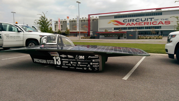
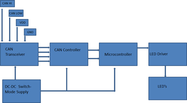
The lighting system currently implemented in the solar car is run using the CAN protocol. A central microcontroller is connected to each signaling light in order to operate each individually. For the lighting system, this requires four wires for each lighting component. Since the solar car is required to have eleven lights (two front blinkers, two side blinkers, two rear blinkers, two front headlights and three rear brake lights) there is a substantial quantity of wire in the car. Since the car needs to be as light as possible to be competitive in races, the team wishes to replace the current wire-heavy central microcontroller CAN configuration with a CAN network that will require two wires, and will daisy chain the lighting circuit boards, nodes, together.
PROPOSED DESIGN SOLUTION
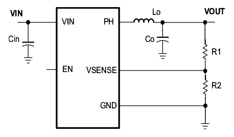
The solution works with the hardware that has been previously installed in the Solar Car. Samples of all necessary components have been ordered for the purpose of building a prototype. Additionally, the team is using EAGLE CAD and Ki CAD software to design and fabricate a printed circuit board prototype. The prototype will be fabricated by the MSU ECE shop for the purpose of testing. A Logic Analyzer will be used to test the functionality of the CAN system for each function and for any possible faults. Given the success of this test, the finished product will be installed in the Solar Car and tested for functionality. This project will be successful if the final design functions as desired by the Solar Car Team.