
Project overview
In this project, our basic concept is to improve and modify the car camera tool system that has been created by the previous team. The system had originally been designed for having four video capturing cameras, each pointed in a different direction. The system was also designed to set up a GPS for debugging error, a keypad to start or stop recording images, USB storage stick that put all memory together to import in computers, an Odroid chip that is running as computing unit with power input at 5V/4 A, and a MicroSD slot, etc.
Project solution
Prototype
In order to build up a reliable and stable video recording tool, Our team has come up with a prototype consist of four high resolutions cameras, a 7 inch HD display screen with HDMI port available, a 5V/4A DC power converter, Odroid Chip and 12V/10A cigarette lighter, etc. The way of building up testing system is illustrated in figure 1.
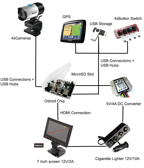
Figure 1
Layout of system
The layout of four cameras along with monitor and computing unit placed in vehicle is illustrated in figure 2. There are two cameras located nearby the infotainment section or instrument cluster of vehicle, one camera is placed closed to the rearview mirror of vehicle while the another one is located in front of infotainment system to focus on video captured ahead. Among two other cameras, one is placed on the dashboard facing outside the vehicle, and this one is intended to give driver the vision to see what he is seeing in front of dashboard. Another one is placed closed to right side of window mirror, and this one is suppose to captured any video recorded during vehicle is in steering or reversing process.
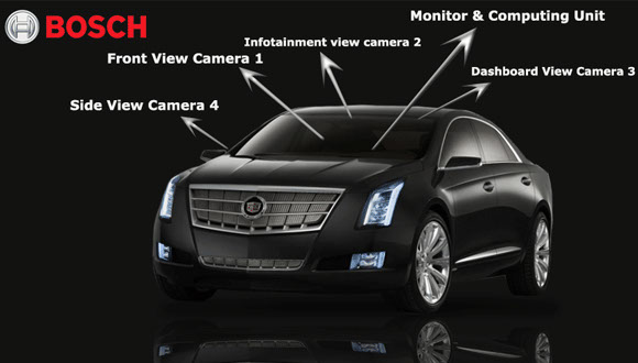
Figure 2
Software
In order to combine four different video stream into one, our team decide to use FFMPEG to implement video capturing function shown in figure 3. Ideally, the system will boot up and bring up a live view of the four cameras connected to the microcomputer. Additionally, a terminal will be called in the background to run the DVR function, which will save the last n minutes of recording. FFMPEG will not be recording from the video cameras directly. Rather, it will be capturing the screen that the live view of the four cameras. This is less computationally commanding and the microcomputer will be under less strain while running.
DVR (Digital video recorder) Function:
1. FFMPEG will be running continuously, recording one minute chunks of video.
a. There will be n total clips depending on how long the save video must be.
b. The batch script will continuously overwrite the video clips labeled 1 through n.
2. When the appropriate switch is pressed, another batch script will run in a different thread concatenating the video into an n minute clip.
Hardware
Certain components of the design, such as the microprocessor (Odroid) and video cameras (Logitech C310 and C270), were received from the previous team's implementation of the design. The layout of hardware components in back of screen are shown in figure 4. Hardware design decisions the team had to make revolved mostly around setting up a user interface for the end user.
Components we added to the design include:
1. Teensy 2.0 Microcontroller: this was used to design a control panel for the design. The Teensy 2.0 was chosen due to the large amount of documentation surrounding the platform. (Arduino)
2. Cherry MX Switches: these switches were used to implement the various controls needed to program; which include, start recording, stop recording, 2 minute DVR, 5 minute DVR, DVR output. These switches were chosen due to their high actuation rate and tactile response.
3. 12V/5V converter: this component was needed to convert power from the car power supply to the microcontroller and monitor.
4. Casing for the recording module: with the addition of components, a case to contain all the components was necessary for the aesthetics of the module.
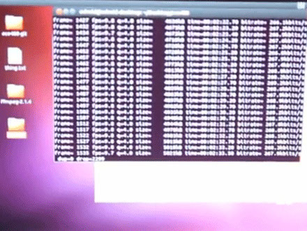
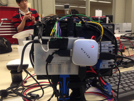
Figure 3 & Figure 4
Budget
The final costs of the design is listed as following in figure 5. Since the last team has already bought the main components for this project. Our cost for final prototype was much less than what our budget allowed for.
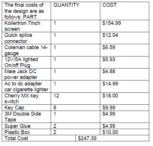
Figure 5
Final Product
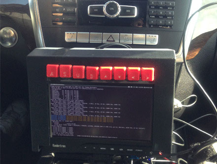
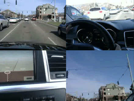
Figure 6 & Figure 7
The final product come with a integrated system is described above; the figure 6 shows how the final system monitor look like when it is placed inside the vehicle, and the figure 7 shows how the output video looks like when it is played with a computer.
In conclusion, the system monitor can record the 2 minutes and 5 minute chunk of video successfully by using FFMPEG, and the power section of system is working successfully and efficiently. The video quality is high enough to read the characters or numbers shown on street signs. Although system can operate for most of function that sponsor required for, the GPS coordinates generates by system is still not accurate and leave out much space to solve further problems.