Project
ECG Demonstration Board
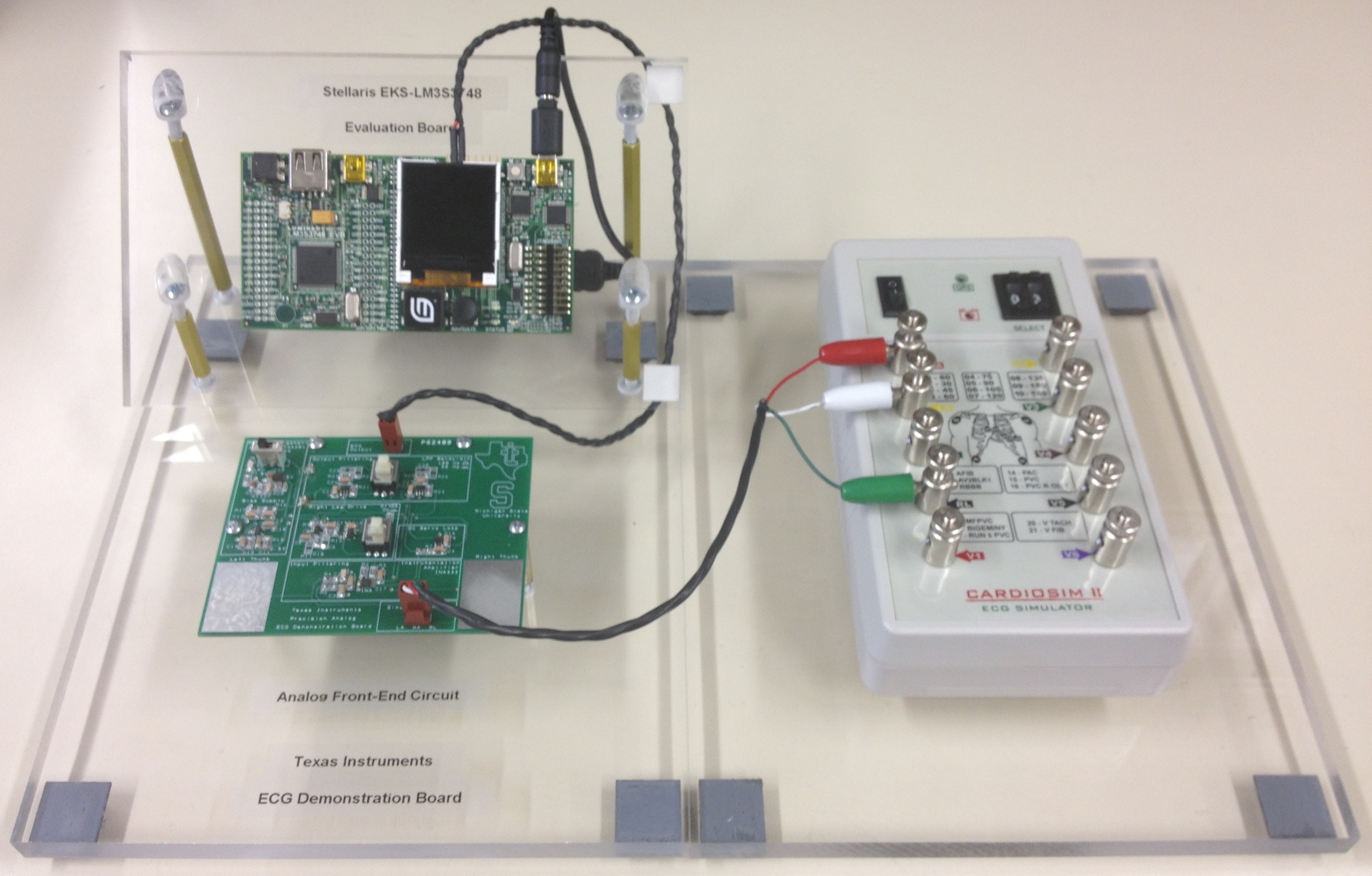
During this project the group went through three phases while developing the
Analog Front End (AFE) circuit. Through several phases, the goal was to
test different solutions for power management, filtering, bandwidth,
physical layout, and different solutions for finger electrodes. On several
boards, extra components (switches, jumpers, test points) were built in to
allow efficient testing and verification of the circuit performance. After
achieving the project goals with the phase 2 board, the team designed,
fabricated, and tested the final phase 3 boards with a final prototype look
in mind. The final boards feature a more evenly spaced layout to showcase the
integrated circuits used from Texas Instrument's precision analog portfolio.
To finalize the demonstration board for TI, the group fabricated and mounted
the AFE and Stellaris EVM to a custom acrylic stand.
Phase 1
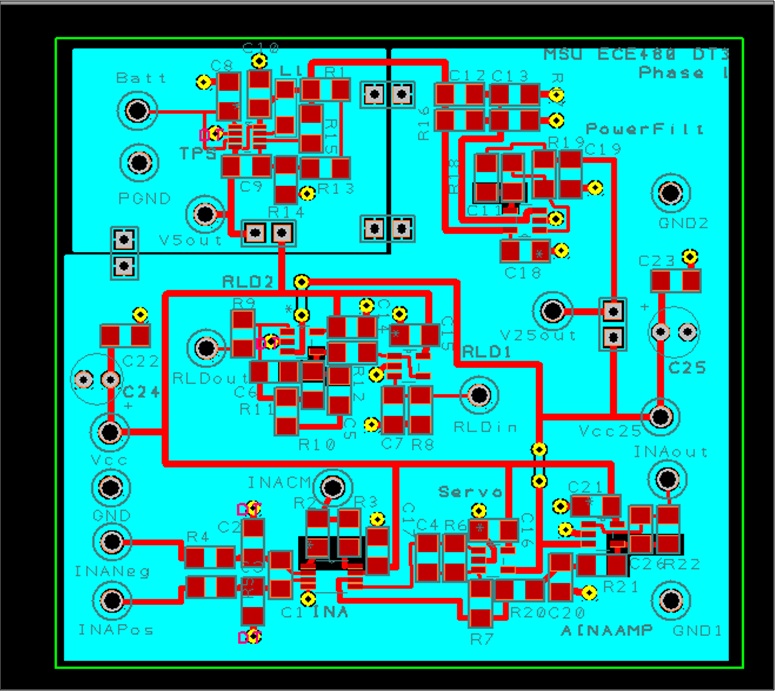
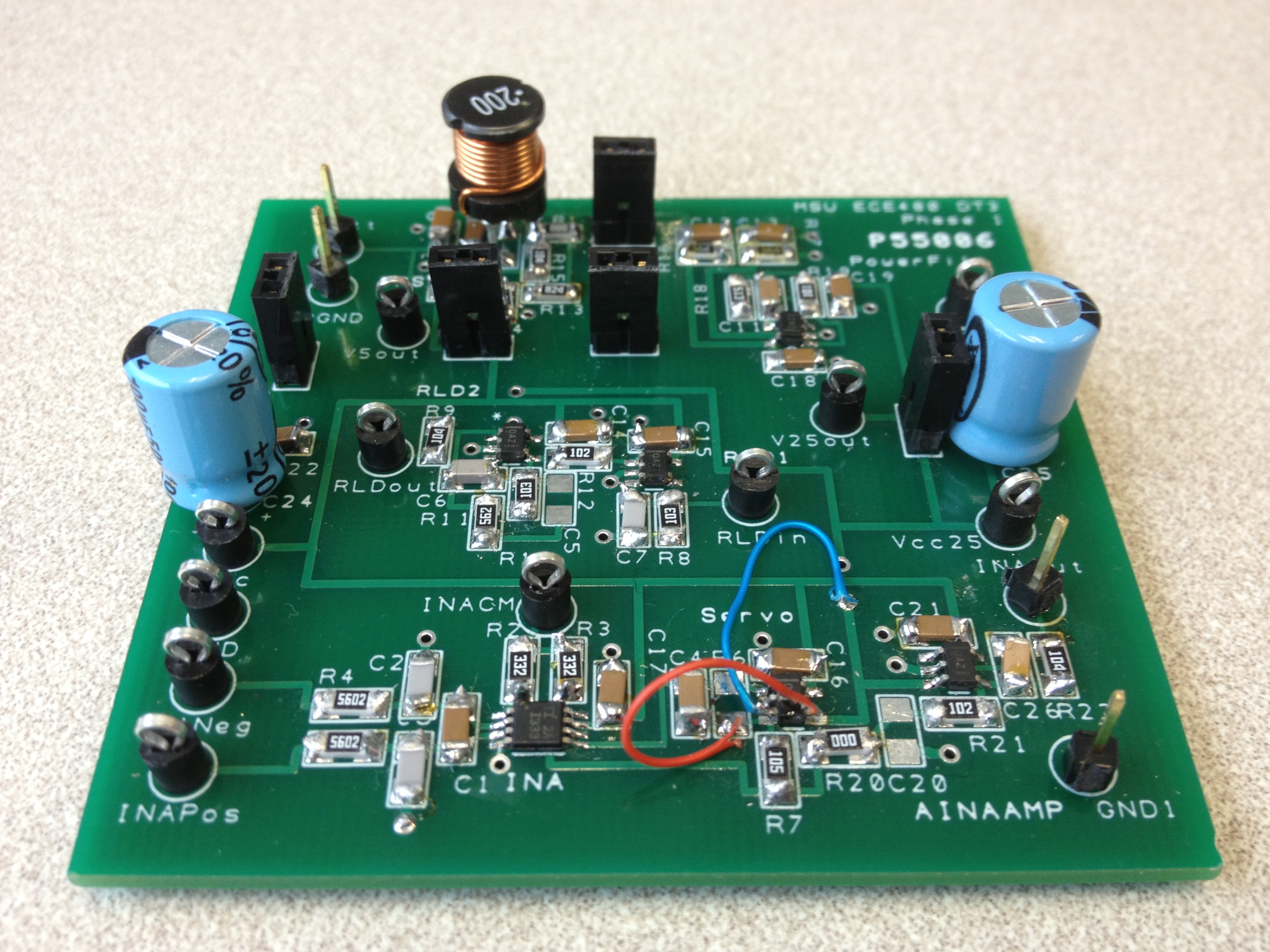
The first phase of the AFE development was meant to be a test circuit,
confirming the circuit performance as seen on the breadboard. The board included
many test points to allow easy access to crucial measurements. The power supply,
analog circuitry, and signal integrity were tested and confirmed successful operation.
Phase 2
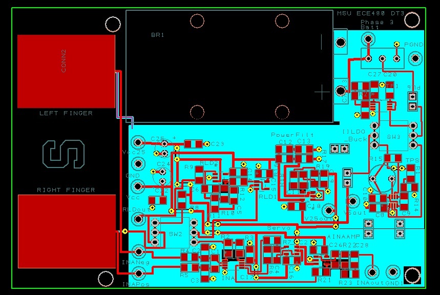
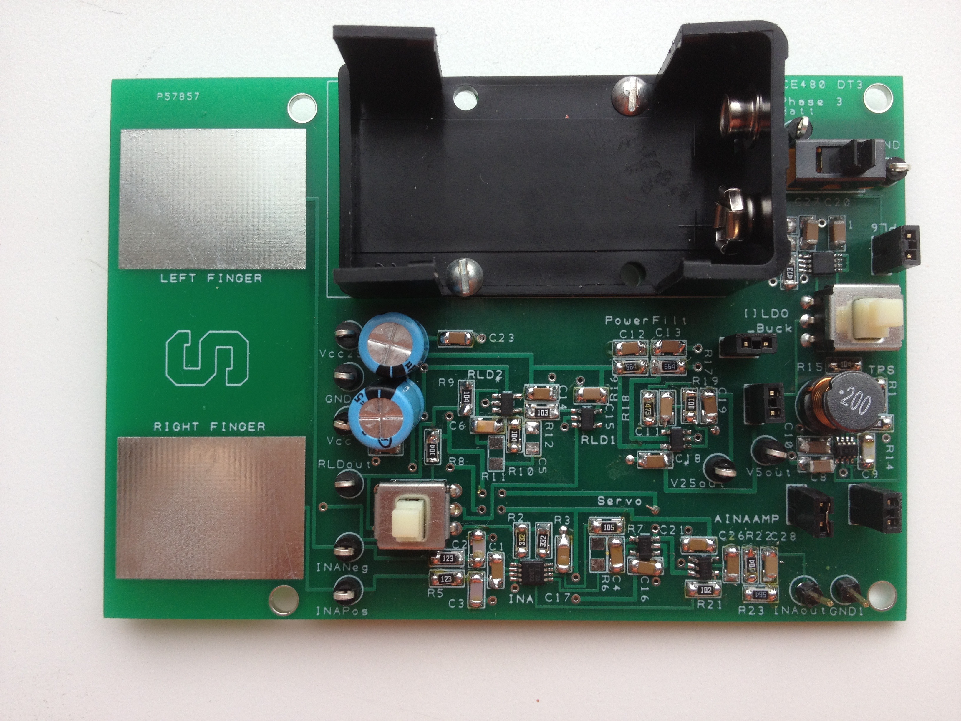
The second phase of the AFE development included a small correction to an error
made in the first phase's PCB layout. New developments in the phase 2 board included
a battery connector to provide portable power to the circuit, DPDT switches to choose
between different power solutions as well as allowing the right leg drive (RLD) to turn on/off.
Finger pads were added to test the ability to obtain a user's ECG signal at the finger tips.
Small header jumpers were left in the power circuitry to allow efficiency measurements to
be made to allow the team to make an educated decision for the power IC used in the
final board. The comparison was made between the buck converter and low dropout
regulator (LDO). The LDO was chosen for the final board due to the simplicity in its layout
and sufficient performance.
Phase 3
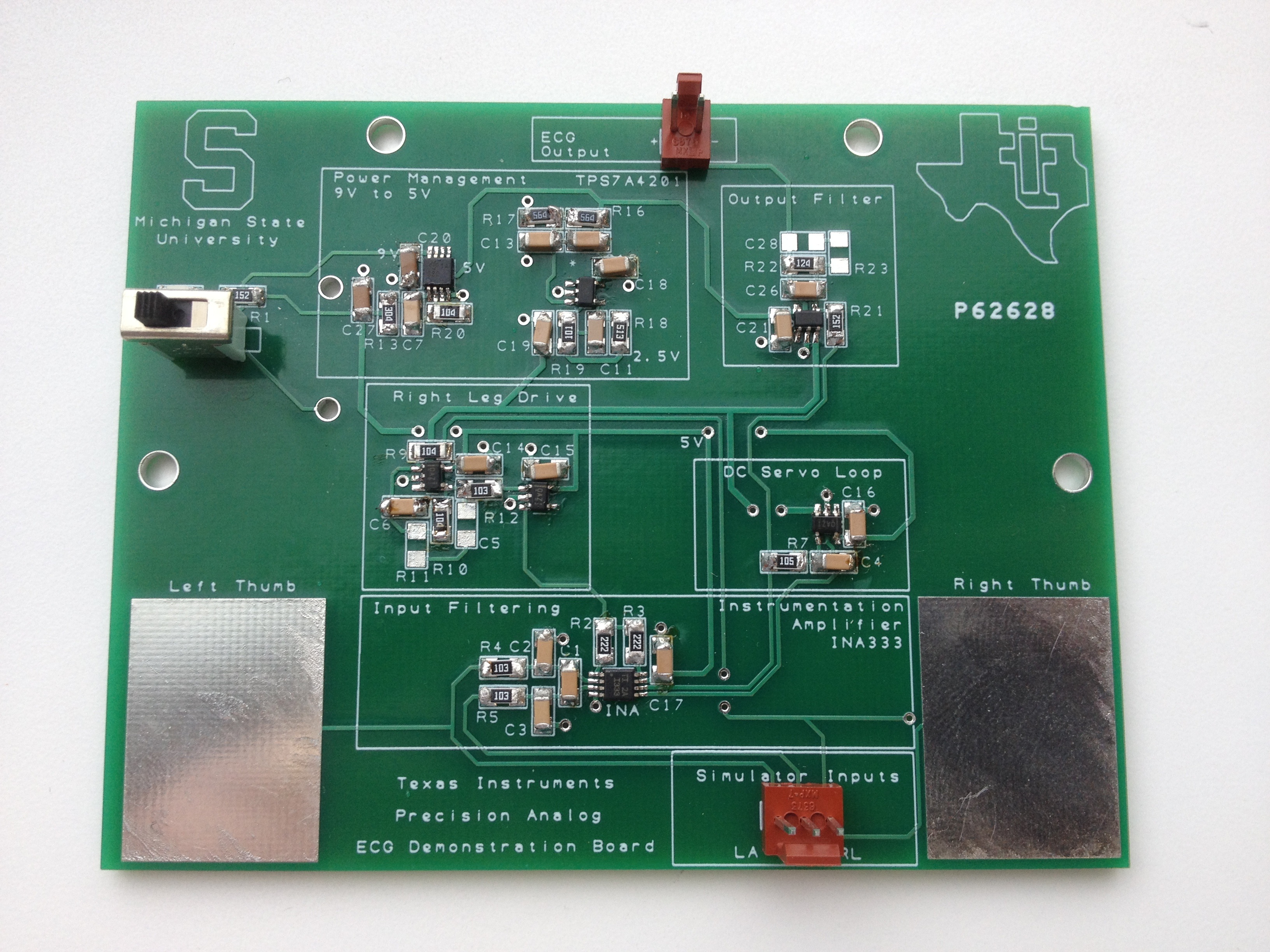
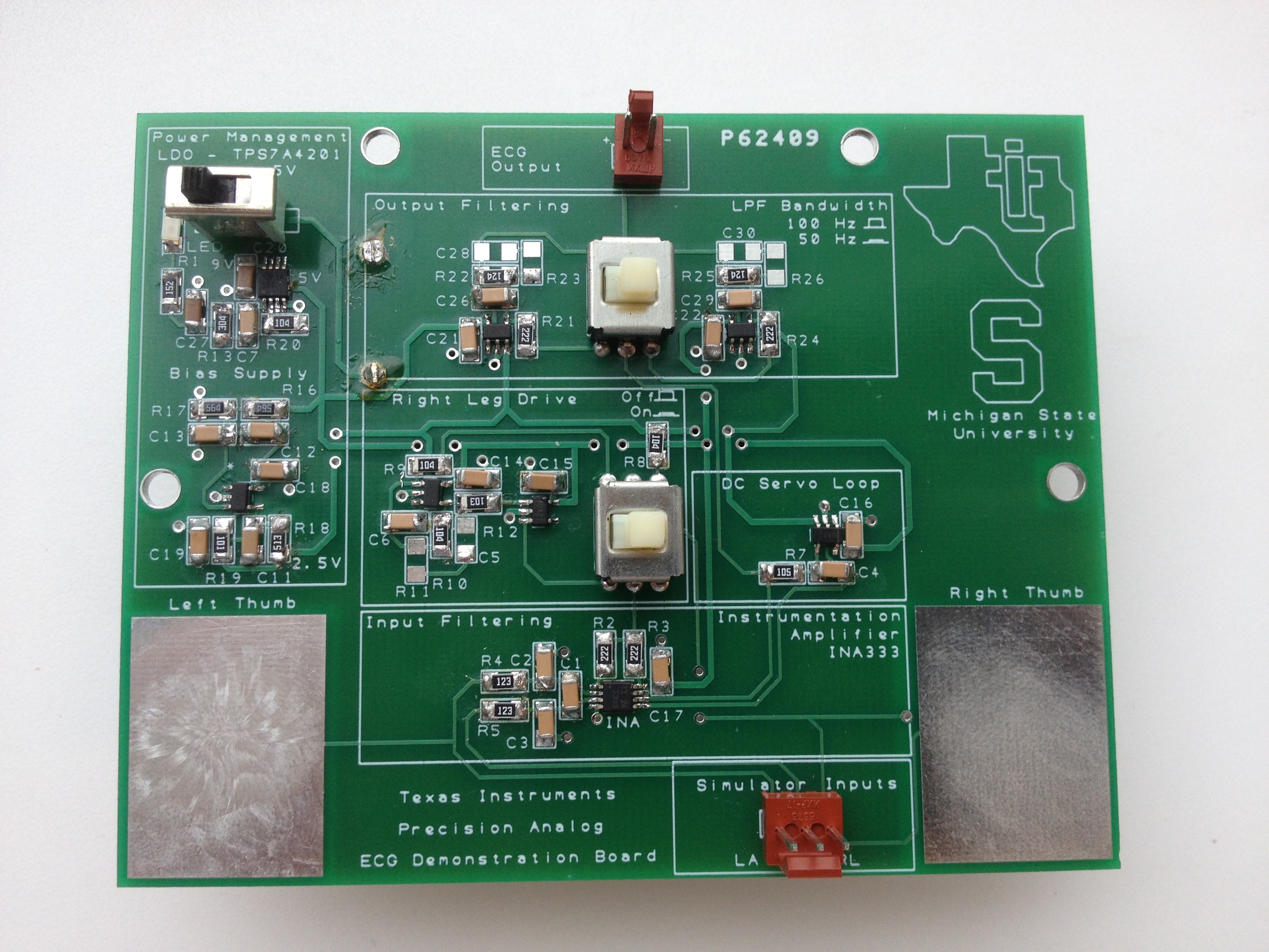
The third phase of the AFE development included the final designs and layouts.
Much of the testing elements (jumpers, test points, etc) were removed. Since the final
deliverable is a display used for demonstrations, the circuit elements were chosen to
be on spread out and labeled to allow users to easily read and follow the board's layout.
Two switches were used to allow the selection of filter bandwidth and to turn the RLD
on/off. Another simplistic version without the selectable features was also fabricated
to give the precision analog group at TI the option to use either board for display.