ECE 480 Team 5 Advanced Communication Bus Breakout Board
Project Description
The current method for testing car modules at Chrysler consists of having all of the modules plugged into one heap on the OBD II box and requires digging through this heap physically when an engineer needs to toggle a module on/off or take a voltage reading. As a result of this inconvenience, the process of module testing is tedious and takes much longer than it should which directly affects time to production. The goal of this project is to develop an advanced breakout box that will simplify the current procedure to get CAN voltage and module current readings by giving each module its own port on the new breakout board where it can be plugged in and its own connection to a communication bus that can be toggled and controlled by an easy-to-use graphical user interface. The graphical user interface should also be able to change what CAN bus the module is connected to and take user input for the voltage supply. Using this device the engineer will not need to physically connect and disconnect the modules. The GUI is also required to store the module and CAN bus data. The new board has to interface with the existing OBD II box and hence requires multiplexing so that signals are not corrupted.
The image below shows interaction of the new breakout board with the existing system.
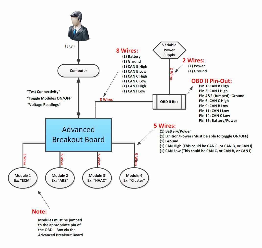
Deliverables:
- The board must be able to be “switch” any module onto any BUS WITHOUT corrupting the BUS communication. - Make Voltage measurements on the BUS lines and current draw measurements on component.Inputs:
- Must use 10 sets of 5 wire screw terminals, one set for each module. - This board must interface with our OBD2 Breakout Box (Details Below).Outputs:
This board must interface with a PC Laptop via USB Port & Connector. In GUI / Hardware: Measure BUS Voltages. In GUI / Hardware: Measure Module Current. In GUI / Hardware: Toggle Modules “ON/OFF”. In GUI / Hardware: Toggle Ignition “ON/OFF”.Connectivity:
The connection between Break out board and pc should be USB connection. GUI need to be user friendly.Notes:
Chrysler Diagnostics Tool is provided to check the communication BUS integrity.

© 2013