PROJECT DESIGN
Principle of Pulse Width Modulation
Pulse Width Modulation (PWM) is a method of encoding the voltage amplitude of a signal within the width of a pulse. Information contained within a pulse width instead of voltage amplitude has the advantage of being less susceptible to both attenuation due to resistance and noise within a transmission line.
The goal of the design project is to transmit the power usage information presented in the amplitude of the transducer voltage between two separated locations with the greatest accuracy possible. PWM was chosen as the transmission method due to its ability to maintain a high degree of integrity of transmitted data regardless of potential signal noise over transmission line lengths ranging up to and exceeding the design length of one half mile. The figure below shows up how PWM works.
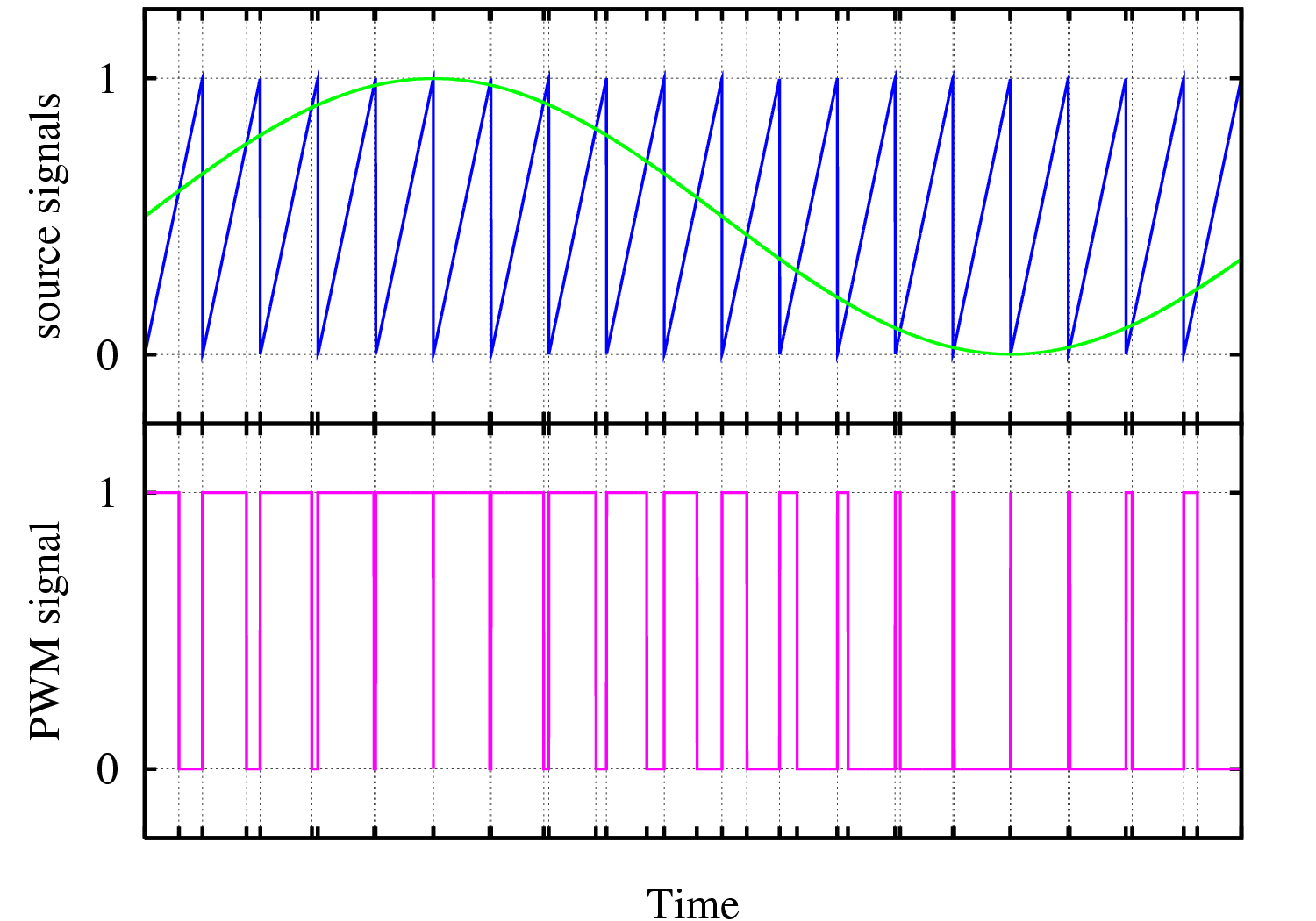
It should be noted that the level of noise which might be present in the transmission line due to electromagnetic interference and other noise sources is unknown and not able to be estimated. There may be a great amount of noise or no noise at all present in the transmission line, PWM was chosen as the transmission method due to the possibility of noise. The PWM signal transmission method along with the shielding on the transmission line should eliminate or at least greatly diminish any external noise should it be present.
PSPICE Simulation
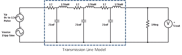
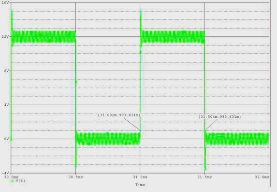
Figure below is a PSPICE simulation of the circuit in Figure above showing the transient result of Vout for two periods of the PWM signal. The high time of the pulse measured in PSPICE can be calculated by measuring the one volt point on both the leading and trailing edge of the pulse. The pulse high time is 31.504ms-31.002ms=502us. The actual high time of the pulse is 500ms evident by the fact that Vp is fifty percent duty cycle with a frequency of one kilohertz. Thus in the example the PWM signal maintains the integrity of the transmitted data to less than one percent error even in an extreme case of noise in the transmission line.