|
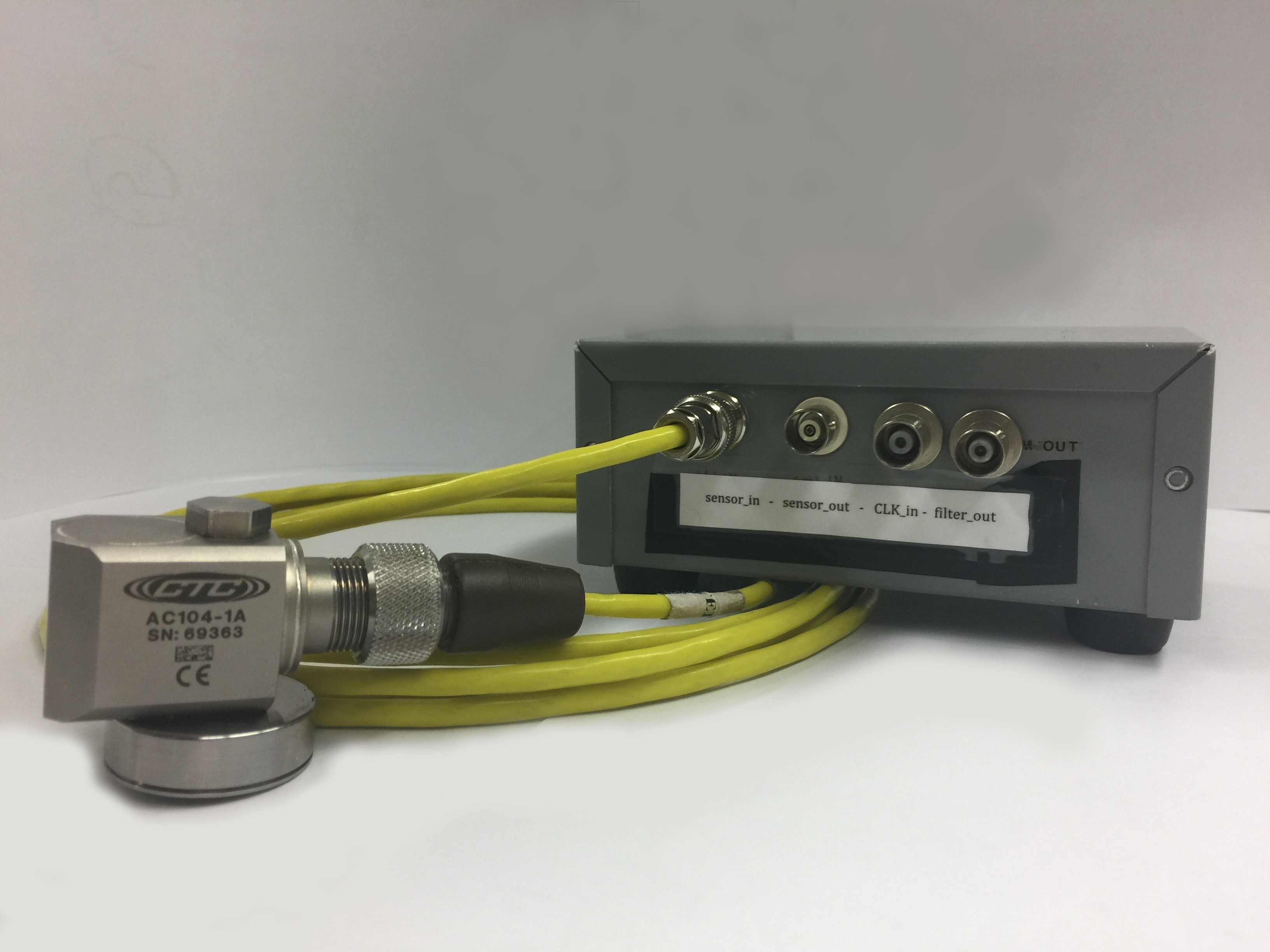
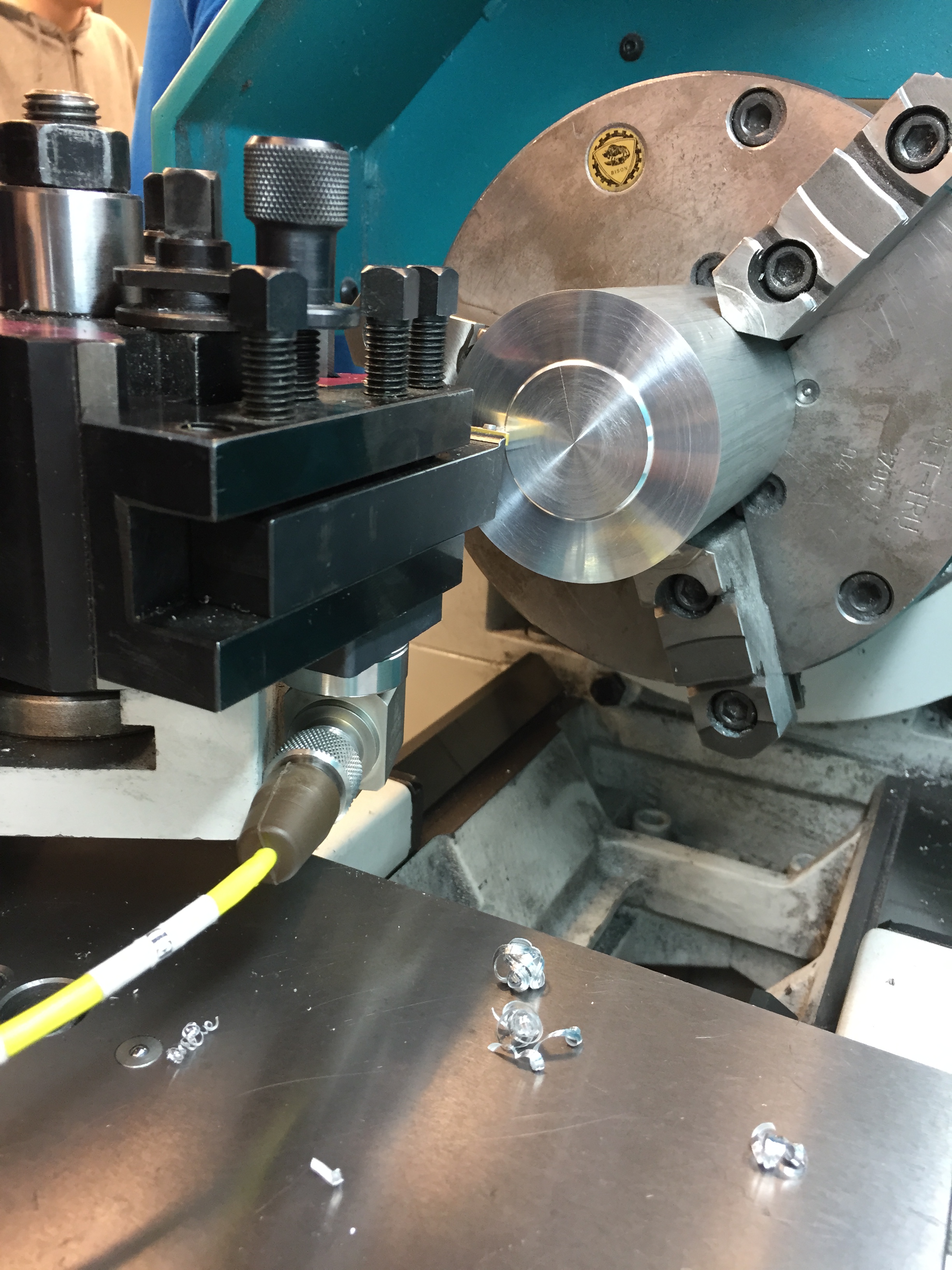
The Design uses an accelerometer from Connection Technology Center, a MAX262 adjustable bandpass filter IC, and an MSP430 microcontroller.
A comparator is used to compare the peak amplitude of the band pass filter to the output of an adjustable reference voltage. The positive terminal of the comparator is fed from the band pass filter output and the negative terminal from a filtered PWM output generated
from the microcontroller. If the amplitude of the filter output surpasses the reference voltage, the comparator output will be driven high, indicating that the magnitude of the signal at a set frequency has surpassed a reasonable level. Otherwise, the comparator output will remain low.
The output of the comparator drives an interrupt enabled pin on the microcontroller, indicating that a milestone in tool life has been reached. Within the interrupt service routine, the pass band of the filter and the PWM reference voltage can be adjusted to check for the next relevant condition and the output to the PLC can be adjusted to reflect the current level of wear.
|