Basic Operations with MSP430
Microcontrollers
Application Note
Qiaosen Huang
03/31/2014
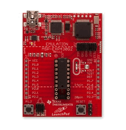
Figure 1. MSP430 LaunchPad
Summary
This application notes will be covering the basic background
knowledge and some advanced techniques for those who are not familiar with
programing MSP430 microcontrollers. Including the required facts to perform
several key functions that were used in this project. Example codes are also
provided. All related background information can be
found in the datasheets provided in reference.
Background
As shown in Figure 1, a typical MSP430 development board
would be looking like that. And it was used in our project prototyping. With
the buttons and LEDs mounted on board, it will be really convenient for starters
doing experiments with the wide range of functionalities of the MSP430. Like
all other microcontroller development board, it also comes with an
USB-to-Serial port and chip. Thus, it is easy for beginners and cheap to upload
and debug codes.
Digital I/O Operation
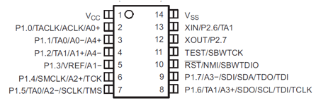
Figure 2. Pin mapping for MSP430F2013
To use the Input/Output functions
of the microcontroller, we will need to determine the corresponding pins we are
about to use, as shown in Figure 2.
|
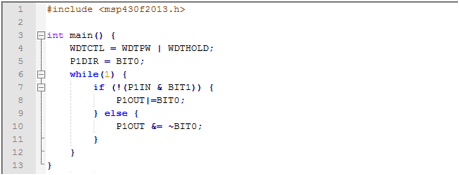
Example: Suppose we have a switch connected to P1.1 and LED
connected to P1.0. And have LED on if button is pressed.
P1DIR will set up the direction for port
1 (output:1,input:0) P1OUT will set the output logic state P1IN will read the input |
Timer Operation
Timer is heavily used in a lot of microcontroller project.
The main usage is to generate precise duration/delay.

Figure 3. Timer_A
Control Register (TACTL)

Figure 4. Timer_A
Capture/Compare Control Register (TACCTL0)
Registers in Figure 3 and Figure 4 are commonly used to set
up the timer. In addition, TACCR0 is
used as the timer count limit, and TACCR1
is used as the counter.
|
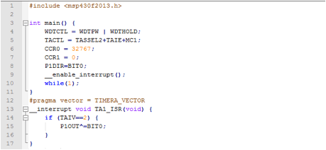
Example: Toggle LED
connected to P1.0 every 1 second precisely.
As said above, we set up TACTL register with 32.7kHz external crystal, interrupt enabled
and up mode. we then write the interrupt routine TA1_ISR, it responses to interrupt
that occurs every 1 second. |
Analog Operation
In the electronic world, there are not only digital signals
but also the analog signals. In order to read the analog signal, we will
utilize the ADC (Analog-Digital Converter) module comes with the
microcontroller.
The 10 bit version, ADC10, is what
most controllers come with. Registers are shown below in Figure 5 and Figure 6.

Figure 5. ADC10 Control Register 0
(ADC10CTL0)

Figure 6. ADC10 Control Register 1
(ADC10CTL1)
|
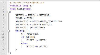
Example Turn on the LED connected to P1.0 if input on A1 (Analog
Pin 1, P1.1) is greater than 2.5V.
ADC10CTL0 was set up such that there is the
ADC will be turned on and has a base reference voltage of 2.5V. ADC10CTL1 was set up such that P1.1 was
selected as analog input pin, and it continuously reads the signal. We then set ADC10CTL0
to start up conversion. |
Reference
MSP430
Launchpad image

MSP430 User Mannual
http://www.ti.com/lit/ug/slau144j/slau144j.pdf
MSP430F2013
Datasheet
http://www.ti.com/lit/ds/symlink/msp430f2013.pdf