ECE 480 DESIGN TEAM 11
Electronic Parachute Deployment System
January 31, 2014
Sponsor: Pete Semig (Texas Instruments)

Facilitator: Joydeep Mitra
Design Team Members:
Michikazu Aono
Max Cooper
Zane Crawford
Qiaosen Huang
Pedro Rodriguez
Jessica Shelby
EXECUTIVE SUMMARY
The Electronic Parachute Deployment System is to replace the traditional parachute deployment method on a large model rocket that employs the use of a multistage parachute, allowing improved consistency and reliability over the traditional fuse system. The system will be controlled by the Texas Instruments MSP430 family of microcontrollers in conjunction with assorted sensors, power supply unit, and parachute deployment system. Lessons learned from the previous attempt at the deployment system during the 2013 Fall semester will be applied during development of the project
Objectives and Design Specification
Introduction
Texas Instruments (TI) has tasked a team of Michigan State University (MSU) students with the reevaluation and redevelopment of a multistage Electronic Parachute Deployment System (EPDS) for a large scale model rocket. The primary function of the EPDS is to activate the parachute deployment process. Once the desired altitude is reached by the rocket, the EPDS will initiate the return of the rocket to ground by deploying the drogue chute. At a secondary point the EPDS will deploy a second parachute that will reduce the impact force the rocket experiences upon landing. To achieve the task, sensor units, power supply unit, and parachute deployment system will be built around a TI MSP430 family microcontrollers(MCU). The team will design, simulate, and fabricate each subsystem while applying lessons learned from the previous semester. The final design will then be integrated in a model rocket and demonstrated to the sponsor.[2]
Background
Rockets have been around for thousands of year, the Chinese being the first to start experimenting with them. Later on, in 1954, model rockets were first introduced by a man named Orville Carlisle. After some time, a man named Vernon Estes started his own company names Estes Industries. Estes Industries was the first major company to launch the model rocket industry, allowing cheap and reliable model rocket kits and engines to families and schools. Today, model rockets are much more safe and technically advanced.
Model rockets are fairly simple in design. They use black powder motors. For the motor to propel the rocket into the sky, first the igniter needs to be heated until the pyrogen lights on fire, causing the propellant to light. The propellant burns and thrusts the rocket upwards. The delay composition will then burn, slowing down the rocket. The rocket then comes to a complete stop at its apogee, or highest point, and the first parachute, called the drogue chute, is ejected just above the motor. This parachute is smaller in size compared to the second parachute and does not slow the rocket much. It is intended to produce more aim and stability for the landing. The second parachute, ejecting behind the nose cone, is deployed once the rocket is closer to the ground. The rocket then slowly drifts toward ground for a safe landing.
The model rocket for this project will include the capabilities of recording information about the flight and deploying two parachutes at specific heights. To perform these tasks, the use of multiple sensors will be used. An altimeter will be included in the PCB to detect the highest altitude the rocket reaches and to alert the microcontroller when to deploy the parachutes. Another aspect of the system will be to record the acceleration at launch. For this, either the altimeter will be used or an accelerometer will be added. These sensors will then be integrated into a system that uses an MSP430 microcontroller to record information and provide parachute deployment instructions.
This project is a slight
continuation of last semester's team project. Many of the same high-level
design ideas will be used in this project. For example, last semester's team
incorporated both an altimeter and an accelerometer. They chose to use an
MPXM2102 pressure sensor for recording their height and enabling the deployment
system, and they used the ADXL330 accelerometer for the take-off acceleration.
As stated before, the decision for this project to include an accelerometer has
not yet been determined. The previous team decided to use voltage regulators in
their design to power the system. They had a 10 V battery supplying an LM2940CT
dropout voltage regulator to convert the 10 V to 5 V. The 5 V then powered an
LM3940IT dropout regulator to output 3.3 V. These voltage regulators provided
the voltages needed, however, they may not have been the most efficient design.
This project will utilize a switching mode power supply to increase the
efficiency of the circuit, although voltage regulators may be an alternative.
The previous team chose the MSP430G2553 microcontroller, however other
microcontrollers will be researched for this project. Finally, the team used a
level 3 Madcow Torrent kit for their rocket model. The build time for the team
took about a month and with difficulties reported along the way. During the
final demonstration, the rocket caught on fire and did not launch. The reported
problem came from the unpredictability of black powder. This project will start
off with a smaller prototype rocket for testing purposes and work its way up to
the rocket model used previously. This project will also allow more time on
rocket construction and will use a smaller version as its prototype. Overall, a
lot can be learned from last semester's project. Knowing last semester's design
allows the team to research the components used along with alternatives, such
as the power sources. That allows this project to utilize the most efficient
components and minimize the cost.
Objectives and Design Specification
This project, Electronic Parachute Deployment System, is a MCU based system that will automatically deploy the built-in parachute when the rocket reaches a certain altitude. For this particular design, the team is tasked with construction of the model rocket, and development of a Printed Circuit Board (PCB) that has a MCU on board to coordinate with all the systems on rocket work as desired.
There are two main functions needed to be implemented.The first will be the ignition system. In order to launch the rocket, it first needed to be ignited. And this will be controller by the MCU. The second, and the most important function will be the parachute deployment. To allow for recovery of the rocket, the parachute will be deployed at the designated altitude automatically.
List of Objectives:
1. Rocket size/payload specification
2. Build rocket
3. PCB design
4. MCU software design
5. Assemble and prepare for first test launch
6. Revise and Final test
Specifications and Design criteria:
1. Number of sensors and Number of Analog-to-Digital Converter (ADC) on MCU.
2. Precision of ADC.
3. Maximum altitude can be reached. Federal Aviation Administration (FAA) has regulations that aerobat operating over altitude of 1,000 feet will need permissions and certifications.
4. Maximum/Optimal payload of rocket
5. Power supply voltage/capacity
FAST Diagram[3]
***To be inserted at a later date***
Conceptual Design
The overall design of the parachute deployment system was constructed look from the top-down. By breaking the overall system down into sub-systems, the design process becomes easier. In figure 1 below, the basic interactions between the different sub-systems can be seen.

Power
The Power sub-system is responsible for supplying properly regulated power to the other sub-systems. This sub-system will likely need to provide various voltages and currents to the other sub-systems. Limiting the number of needed voltages between the different sub-systems would simplify the design of the power system.
Since the electronics are going up several hundred feet in the air, the simplest and most practical power source option available is batteries. A nine volt battery will likely be our final choice as it provides a fair amount of ampere-hours, it is in a compact package and it would provide enough voltage to the other systems.
To accommodate devices within the overall system that use less than nine volts, a switch mode power supply will be constructed. Using the common buck topology, shown below, the 9 volts could be regulated down to 5 volts or 3.3 volts as needed. The major benefit to this approach is the voltage step down will occur with greater than 80% efficiency. Other common approaches of voltage step-down, such as using transistor regulator or a zener diode are far less efficient. The buck convert would likely cost more to implement, but the advantages could be greater.
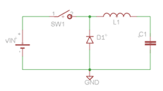
Figure 2: Simplified Buck Converter
Sensors
The sensors are our raw input into our system, and will be selected carefully. The current design would have two altimeters and a single accelerometer. The accelerometer is largely responsible for detecting the force of the rocket launch. A secondary use of the accelerometer could be to gather flight data that could be analyzed later. Having two altimeters would allow the parallel use of one analog altimeter and one digital altimeter. These altimeters are pressure sensors that sense the barometric pressure and output a particular ¡®altitude¡¯. The barometric pressure varies as elevation changes, but also as temperature change.
The changes in temperature could present an issue when calculating the current altitude. It is for this reason that two altimeter will run in parallel. The digital altimeter will be highly accurate and will automatically output a temperature adjusted reading. The downside to this sensor is, it is slow. The digital sensor is only capable of produce a few output a second. This would not give the fast traveling rocket enough resolution in its current height. The analog altimeter is fast, but it needs to be properly calibrated for temperature and starting pressures every launch. Since these parameters (temperature and starting pressure) change between flights, calibrating the analog altimeter becomes tedious. By running these altimeters in parallel the benefits of both can be achieved. The digital altimeter will be read by the microcontroller before the launch of the rocket. This digital value will then be used to calibrate the analog altimeter within the software. Then the analog sensor will be used throughout the rocket flight.
MSP430 Microcontoller
The MSP430 microcontroller from Texas Instruments is at the center of this project. This microcontroller takes in the various sensor inputs filters them and ultimately outputs a signal to deploy a parachute.
Using the analog to digital converts (ATD¡¯s) on the MSP430 will allow the interfacing of the analog accelerometer and the analog altimeter. These ATD converters will need to be properly set up and adjusted within software. The data collected from the sensors will be stored on the microcontroller for later retrieval. The sensor data can later be extracted from the microcontroller and analyzed to reveal the rocket¡¯s flight characteristic. If time permits, there could be additional functions added to provide a USB connection to exchange flight data.
The overall software on the microcontroller during flight will be constructed like a simple linear state machine. Once a certain parameter is met in a particular state, the microcontroller will move the next state. This process will continue until the parachute is untimely deployed. After the parachute is deployed, data will still be collected and stored about the rocket¡¯s decent.
The basic state machine functions triggers would be:
0) Idle state
1) Detect Launch using accelerometer
2) Start polling and recording and altimeter data.
3) When the altimeter starts detecting a drop in altitude deploy the drogue parachute
4) When the altimeter reaches a certain threshold height deploy the main parachute.
5) Detect landing with accelerometer.
6) Store recorded flight onto flash memory.
7) Create velocity data by looking at changes in altitude vs. time
Figure of state flow chart to be added in future revision
Parachute Deployment/ Rocket
A successful parachute deployment all starts from a properly assembled rocket. The choice of rocket does impact all the other sub-system. The choice of rocket will determine the physical dimensions of the electronics we can put inside. The rocket will also have certain payload capacities which may put a constraint on other sub-system.
There will be two pre-designed rockets kits built by the team. The first rocket will be a small prototype and will give good rocket building experience as well as launch experience. This smaller rocket will deploy its own single parachute automatically, but provides a payload bay. These features provide an opportunity to test electronic component within the rocket, without having them actually operate the parachute. Once proper testing has been done on the smaller model, the larger and final model rocket will be built and used.
The larger model will contain two parachutes and will be controlled by the tested electronic design. The parachutes will be deployed during flight using small explosive charges. This is the typical method of parachute deployment of this size.
Figure of rocket¡¯s cross-section to be added in future revision
Risk Analysis
The proposed project has two main aspects of the project that warrant analysis of their risk to the safety of humans, especially the project team, and the environment in which the project will be built. The components namely are the power source of the booster pack and the rocket itself. This section will briefly examine the risks of each component and some precautionary measure that will be taken to ensure the safety of all who might be affected by the project.
A power supply is a necessary component of this project. The booster pack and MSP430 Launchpad will both need a small power supply. This will supply the voltage and current needed to operate the chip and any other devices that are a part of that circuit. In addition to the booster pack and Launchpad, there will be a small source of ignition within the rocket to separate the sections of the rocket from which the drogue and main parachute will be deployed. One method of separating the sections is to use a small charge of loose black gunpowder. Alternatively, devices like an e-fuse can be used as a charge that will apply enough force to separate the sections. Both methods will require a larger source of power for ignition than the boosterpack and Launchpad *** double check this fact***.
Team members working on the project will need to be diligent when designing and installing the power supply. Strict adherence to the safety guidelines outlined by ¡°Electric Safety,¡± provided by the Michigan State University ECE shop, will be mandatory. Failure to do so may result in damage to the circuit, as well as damage to the team member working on the project. Improper handling can cause current to flow across the body, which only needs 6 µA to cross the threshold of pain (ES citation here).
In addition, according to a report done by the ECE shop, any batteries that are used for the power supply should be properly stored to avoid problems such as accidental discharge and well as explosions from a material breakdown.
The rocket presents numerous risks to the safety of not only team members, but the members of the surrounding community in which the project will be tested. The team members will need to be careful when assembling the rocket to avoid injury. However, the larger risks come from the launch of the rocket. The assembly of the housing for the rocket motor, as well as the installation of the rocket motor, is very important. Failure to secure the housing will cause the rocket motor to do internal damage to the rocket. This damage can extend from destruction of the booster pack and Launchpad to the combustion of the rocket as a whole, which may result in fire and shrapnel. In addition to the proper assembly and installation of the rocket motor, the fins and wings of the rock must also properly installed to ensure a smooth and predictable flight. Failure to do so puts anyone and anything in the vicinity of the launch site at risk of damage from a flying projectile.
Protocols will be in place to ensure the rocket launch is safe and has a minimum risk to those near the launch site and the land surrounding the launch site. The National Association of Rocketry (NAR) has a list of guidelines that will be adhered to when designating a launch site. The most important points to follow to minimize risk are to launch from an outdoor location that is clear of any obstacles and is prepared to minimize fires. Depending on the motor size, the launch site must meet the minimum dimension size specified by the NAR, with team members being at least 25% of the dimension radius away from the rocket at launch. The team must also be prepared to reschedule launches that occur under unfavorable weather, including clouds and high winds.
Project Management Plan
The parachute deployment system contains several different partitions that will allow each team member to contribute to an influential portion of the project. The major sections for this project include rockets, sensors, microcontrollers, power, ignition system, deployment system, and analog circuitry. By dividing each of these critical functions to the rocket into a different set of group members, the team will be able to work both individually and collaborate with each other to ensure continuity with the project. The team has not currently assigned individual sections to the project. Under each section, the student will be expected to adequately research their portion, report their expected budget and proposal to the team, assemble the parts, test the individual components, and ensure it operates properly in the full scale system.
The parachute deployment system will require finding a proper launch site. This will take time to research proper launch site due to the various regulation concerning large scale rocket launches. Resources to build the design have been have been found. The electronic components for this design can easily be found online through larger electronic distributors. Some Texas Instruments specific components will be provided by our sponsor for our use. Most of the rocket supplies can be found online at ¡°www.apogeerockets.com¡±. Printed Circuit Boards (PCB¡¯s) will need to be fabricated throughout the design process. These PCB¡¯s can be manufactured through Advance Circuits or for slightly cheap through oshpark.com. These listed resources will provide everything needed for the project to be completed on schedule.
Budget
The team is provided with a $500 budget for the project, of this nearly 60% of the budget will be spent on the model rockets to test the system on. Additionally the sponsor is requesting the team to conduct a mini project ensuring members are competent in the simulation of circuits and PCB design, this project is currently estimated to use 20% of the team budget.
Table 1. Pre-proposal Budget estimate
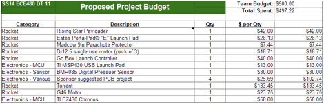
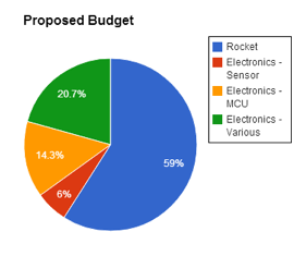
Figure 3. Proposed Budget Distribution
References
"History of Model Rockets." 321Rockets. Web. 30 Jan 2014. <http://www.321rockets.com/model-rocket-history.html>.
"How Rocket Engines Work." Apogee Components. Web. 30 Jan 2014. <http://www.apogeerockets.com/Tech/How_Rocket_Engines_Work>.
¡°Model Rocket Safety Code¡± National Association of Rocketry. Web. 30 Jan 2014
<http://www.nar.org/NARmrsc.html>.
¡°Chapter 31. Rocket and Launch-Vehicle Operations.¡± U.S. Department of Transportation Federal Aviation Administration. Web. 30 Jan 2014
<http://www.faa.gov/air_traffic/publications/atpubs/AIR/air3101.html#air3101.html.1>.
¡°Electrical Safety¡± Electrical and Computer Engineering MSU. Web. 30 Jan 2014
<http://www.egr.msu.edu/classes/ece480/capstone/f13/safety.pdf>.