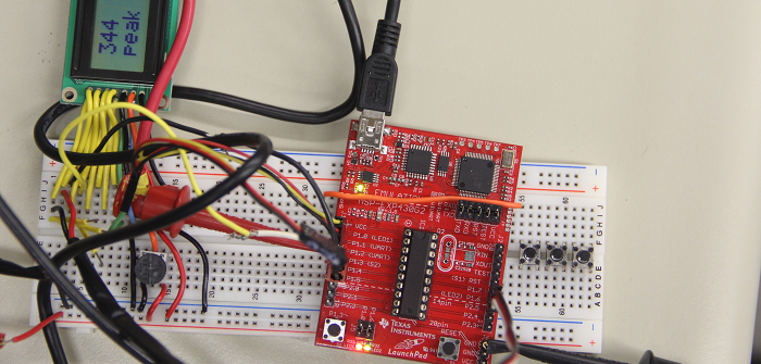

Often times, when shipping items worldwide, shipping containers can get bumped and thrown around carelessly.
This can sometimes lead to damaged products. To monitor the movement of these shipping containers, the G-Meter was designed.
The overall goal of the G-Meter is to sense a g-force and then output that g-force reading to a LCD.
The G-Meter was designed to monitor the linear acceleration of the device in the horizontal axis.
Once the G-Meter experiences a g-force, the G-Meter will then display the value of the g-force on its LCD.
The G-Meter will work in two separate modes.
The first is a Real Time mode which will update the LCD every five seconds with the maximum g-force value that is experienced over that five second interval.
Within this mode, the G-Meter will also calculate and display the Root Mean Square (RMS) value over the same five second interval.
In addition, the G-Meter will have a freeze button which will allow the user to hold the current g-force reading on the LCD.
The second mode is the Peak/Hold mode. In this mode, the G-Meter will store the maximum value that is experienced over the time duration that the G-Meter is active.
Similar to the Real Time mode, the RMS value will also be displayed on the LCD.
In addition, the G-Meter will store the exact date and time when the maximum g-force value was recorded.
Included in the Peak/Hold mode is a reset button which will allow the user to reset the current maximum g-force reading.
By using the G-Meter, users will know exactly how many g-forces their shipping container experienced while their container was being transported.
1.2: Background
There were multiple initial ideas for the components that would be used to construct the G-Meter.
The heart of the G-Meter is the accelerometer, since that is the component that is sensing the g-forces.
Accelerometers are designed in two forms, analog and digital.
Typical accelerometers are designed to work in three-axes, but since the G-Meter is to work in a single-axis, a three-axis accelerometer would be unnecessary.
After doing much research, the team opted to purchase both an analog and digital accelerometer.
Due to excessive factory lead time, the digital accelerometer would not be able to arrive before the project needed to be completed.
This resulted in the analog accelerometer being used to construct the G-Meter.
To fit the necessary specifications for all of the components used in the G-Meter, a step-up converter would need to be used.
A step-up converter would allow the initial three volts of the two AA batteries to be stepped up to five volts.
This was necessary is powering the analog accelerometer as well as the LCD.
By using a step-up converter each component in the G-Meter could have a supply of three volts (pre-step-up converter) or five volts (post-step-up converter).
Based on the availability of products on the market that applied to the G-Meter, the use of a step-up converter was a logical solution.
The final design concepts for the G-Meter were designed to fit in an encasement that is approximately 12 cubic inches.
This would allow for the G-Meter to be a sleek device that could be attached to shipping containers which would then sense the g-forces experienced by the G-Meter,
as well as the shipping container.