


Introduction to the hardware The hardware for this project consists of a solar irradiance sensor, microcontroller and power source. These were integrated together to produce a wireless sensor network that can span over ten miles. The software program, communicates with the wireless sensor network to create a simulation of cloud movement around the area of the solar panel. The sensor
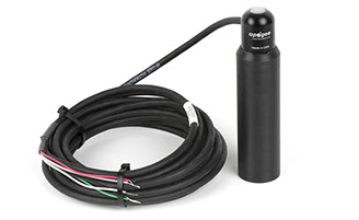
The sensor selection was a critical part of this design. The sensor will log values of the current solar irradiance, which will be used in the software to detect cloud patterns. The sensors will be outside 24-7 and therefore will have to be durable as well as sensitive to the changing irradiance values. The apogee all weather pyranometer is a solar irradiance sensor that satisfies these conditions. It has a heater for the winter months and is self powered. The Microcontroller
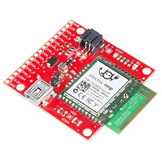
The microcontroller is the most essential part of the hardware design. It will serve as the middle man between the sensor and the early warning software program. The microcontroller must contain the ability send data wirelessly to a server that is accessible by the software program. The microcontroller of choice is the electric imp 002. This microcontroller is able to send data to an accessible electric imp server via a Wi-Fi connection. With this functionality the data is readily available for the early detection software. The Power Source
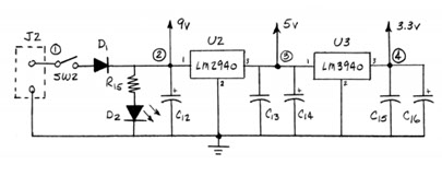
The power source used in the sensor network is very familiar to fellow ECE 480 students. It is the same power supply circuit created in lab 01 of the class. This is the best option because the circuit provides all the current and voltage required for a working prototype once the input wall wart is upgraded to a 9V, 1.5A output. This circuit provides 3.3V to the microcontroller and light sensors by stepping down 9V twice, first to 5V then down to 3.3V from there using TI’s LM2940 and LM3940, respectively.