
Our Design
The purpose of this project was to design a small self-contained device that will open or close a relay contact in the event that a present G-level is “exceeded”. The device uses a 3-axis accelerometer and associated data acquisition and processing electronics that can measure G-levels. The G-Switch has two operational modes: peak and RMS level detection both with 8 different trip levels. There are two heavy-duty screw terminal strip connections connected to two relays—one set to normally open and one normal closed—that will activate whenever the present G-level or RMS-level exceeds the set trip level. There are also two flashing LEDs on the device—one red and one green—that communicate with the user whether or not the device has been tripped. Over the course of the past semester, Team 7 was able to successfully design and build a working g-switch.

Block Diagram of the User Settable G-Switch
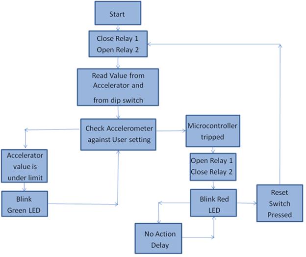
Microcontroller Code Flow Chart
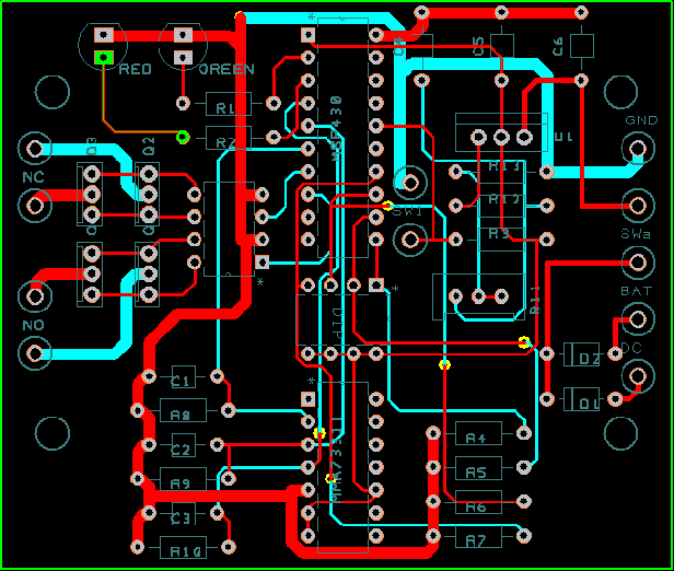
PCB Design Layout